Installation instructions for the ATI Diesel Super Damper, part #918888, a high-performance harmonic balancer for Dodge Cummins engines. The Super Damper controls crankshaft torsional vibration far better than a stock damper. This guide lists the required tools and the assembly and torque steps.
Download the Original PDF Manual
Tools Required
- Damper installation tool
- Torx T-40 Plus bit
- Torque wrench (ft-lbs & in-lbs)
- Blue Loctite 242 (or similar grade)
Additional tools required, depending on damper
- Torx T-45 Plus bit
- Allen wrench sockets
- 3/8″ 12-point socket
- 5/16″ 12-point socket
- Red Loctite
Assembling the Damper to the Hub
IMPORTANT: All bolt holes must have a bolt installed. The damper hub-to-damper shell assembly fit is held to an extremely close tolerance.
- The Super Damper shell assembly is indexed to the crank hub with an offset hole, marked by an indent dimple on the front of the hub and by an arrow on the front face decal. These must be aligned for proper assembly.
- Start the damper onto the hub. If you are exactly straight, it will slip right on — you may need to use your palms or fists to get it to go all the way back. Once the shell assembly is on enough to start two 5/16″ countersunk flat-head bolts, do so 180° apart and “snug” them slightly, opposite each other, so the shell will “walk” on. The shell assembly will slip on as the bolts straighten it out.
- Start the remaining countersunk flat-head screws — (7), (4) or (2), depending on the pulley-bolt configuration — in the remaining tapered holes. Draw the damper assembly onto the hub evenly. Torque the six (6) flat-head screws to 16 ft-lbs. Use Blue Loctite 242 and the proper Torx-40 / 45 Plus bit in most cases.
WARNING: T40 PLUS is not a standard Torx bit. Using a standard bit will ruin the head of the bolt and make it nearly impossible to ever get the bolts out.
Balance Information
Most OEM-built engines are factory balanced with the damper and flywheel installed. OEM dampers may have been drilled from factory specs to balance the engine at the factory. If you have the original damper that came on the engine, or your engine was balanced with a replacement damper installed, it is desirable to match-balance the new damper to your old unit. Your OEM damper must be in good condition, and you must be certain that the outer ring has not moved. ATI can perform this service for $60.00.
NOTE — Balance shops: When balancing externally balanced units, use only the hub and weight, or the hub and shell with the weight attached. The inertia ring and inner/outer shell are factory zero-balanced during manufacturing. The inertia weight is held in place by elastomer rings, so it will move during the balance job, and it needs to spin for the first time after installation to center itself. ATI manufactures all externally balanced dampers to the heavy side so the balance shop can remove weight to match OEM.
Zero-balance units should not be drilled and should not be on the crankshaft for balancing — install the damper at engine assembly. Because the inertia weight in the Super Damper is not bonded, it may not be on center until the engine is started. The damper may show out of balance until the engine reaches 2000 RPM for the first time and the inertia weight centers itself.
Installing the Hub or Damper-and-Hub Assembly to the Crankshaft
- Inspect your crankshaft for burrs, nicks, etc., and file to clean up.
- Stone or file a slight radius on the end to break the sharp edge.
- Inspect your key and replace as necessary.
- It is highly recommended that you use anti-seize lubricant on the crankshaft before hub installation.
- Press fit of the hub to the crankshaft is vital to transfer harmonics to the damper assembly. Use the recommended press fit below.
Recommended Press Fit
- Crankshaft OD 1.2510″ – 1.3750″ → .0008″ to .0011″ interference
- Crankshaft OD 1.3750″ – 1.6000″ → .0007″ to .0009″ interference
- Crankshaft OD 1.6010″ – 2.0000″ → .0006″ to .0008″ interference
- Crankshaft OD 2.0010″ – 2.5000″ → .0005″ to .0007″ interference
All cranks must be checked with micrometers and the hub with a dial bore gauge to verify fit. Most OEM cranks are held to +/- .0002″, while most aftermarket cranks are held to +/- .0005″. Hub bores are tight to accommodate aftermarket cranks, and most hubs will require honing. ATI can perform this service for $40.00.
- Rear-mounted accessory pulleys must be placed on the rear of the hub before installation. Insert (3) 5/16″ or 3/8″ pulley bolts through the front pulley, through the damper body, and through the 3/8″ tapped holes in the hub. If the damper is supplied with 3/8″ rear pulley bolts (i.e. supercharger versions), they will pass through a hole clearanced for this size bolt in the hub. These bolts thread into the pulley and draw it up tight to the rear of the damper hub. Use Blue Loctite 242 on all bolts and torque any 3/8″ bolts to 28–30 ft-lbs and 5/16″ bolts to 16–18 ft-lbs, evenly.
- Press or install the damper-hub assembly onto the crankshaft using the proper install tool. (Refer to your damper installer/removal tool instructions to properly press the damper onto the crank.) If you need to install the hub onto the crankshaft first, use the proper installer.
Because of clearance issues in some vehicles and certain design features on some ATI dampers, the hub may need to be installed before the damper body can be affixed to the hub (e.g. some Cummins and Fords). With these applications, make sure any rear pulley is placed on the rear of the hub before bolting the hub to the crank. On four-bolt-mount hubs, the hub-to-crank bolts must be tightened before the damper assembly is installed.
- Important: New crank bolt(s) should be used for all installations. Install the OEM crank bolt(s) along with the correlating washer(s) and torque to the manufacturer’s specifications. If longer crank bolts are required, they will be provided with your damper — torque these to the manufacturer’s specifications as well.
WARNING: A single long bolt should not be used to retain both the drive mandrel and the damper to the crank, as it will stretch when it gets hot.
- For front-mounted crank pulleys, use the 3/8″ 12-point, 5/16″ Torx, 5/16″ 12-point, or button-head bolts provided. Insert the (3), (4) or (6) bolts through the pulley and into the hub. Make sure the pulley is located on the damper hub ID or on the face register. Use Blue Loctite 242 on all bolts and torque any 3/8″ bolts to 28–30 ft-lbs and 5/16″ bolts to 16–18 ft-lbs, evenly. For applications where an external balance weight is bolted to the front pulley, use care in positioning the pulley in the right orientation — it will only go on one way with the bolts provided.
IMPORTANT: These bolts must be installed and torqued even if no pulleys are used.
Torque Specifications
- Damper flat-head screws (shell to hub) — 16 ft-lbs
- 3/8″ pulley bolts — 28–30 ft-lbs
- 5/16″ pulley bolts — 16–18 ft-lbs
- OEM crank bolt(s) — per the engine manufacturer’s specifications
Damper Mandrels and Mandrel Bolts
ATI dampers, in all cases, must be retained to the crank with a standard-length bolt torqued to the manufacturer’s specifications. Long bolts used to retain drive mandrels stretch when they get hot and should not be used. ATI manufactures special hubs for many engines that put the bolt below flush and allow drive mandrels to be located and bolted to the 3 pulley-bolt holes. ATI can duplicate your existing long-bolt drive into a bolt-on mandrel type in one week, without plating. Mandrels are drilled and tapped to retain pulleys and dry-sump drives.
Removal of Your Super Damper
- Remove at least (3) bolts from the damper on an equal pattern, for use with the damper installer/removal tool.
- Refer to the damper installer/removal tool instructions to remove the damper. For applications that mount to the crank with 4 bolts, the damper body must be completely removed from the hub first.
Maintenance — When the Damper Needs New Rubber
Drag-race engines subject the damper to low total cycles at intermittent intervals. Elastomers in all units under 800 HP that have been inspected easily meet the ten-year requirement. Nitrous and drag-racing engines in excess of 800 HP that see frequent track use should be inspected and rebuilt annually.
Recommended maintenance schedule
- Street and drag-race motors (up to 800 HP) — rebuild the damper every 10 years.
- Above 800 HP, blown, or nitrous racing — rebuild the damper annually.
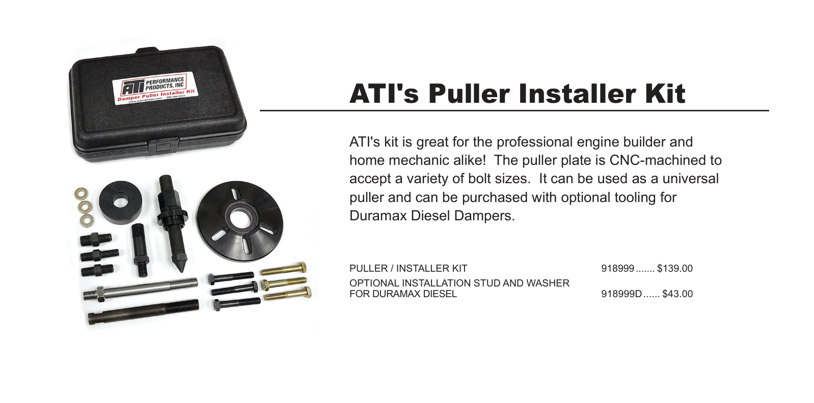
Puller / Installer Kit
ATI’s Puller / Installer Kit is great for the professional engine builder and home mechanic alike. The puller plate is CNC-machined to accept a variety of bolt sizes. It can be used as a universal puller and can be purchased with optional tooling for Duramax diesel dampers.
- Puller / Installer Kit — part #918999
- Optional installation stud and washer for Duramax diesel — part #918999D
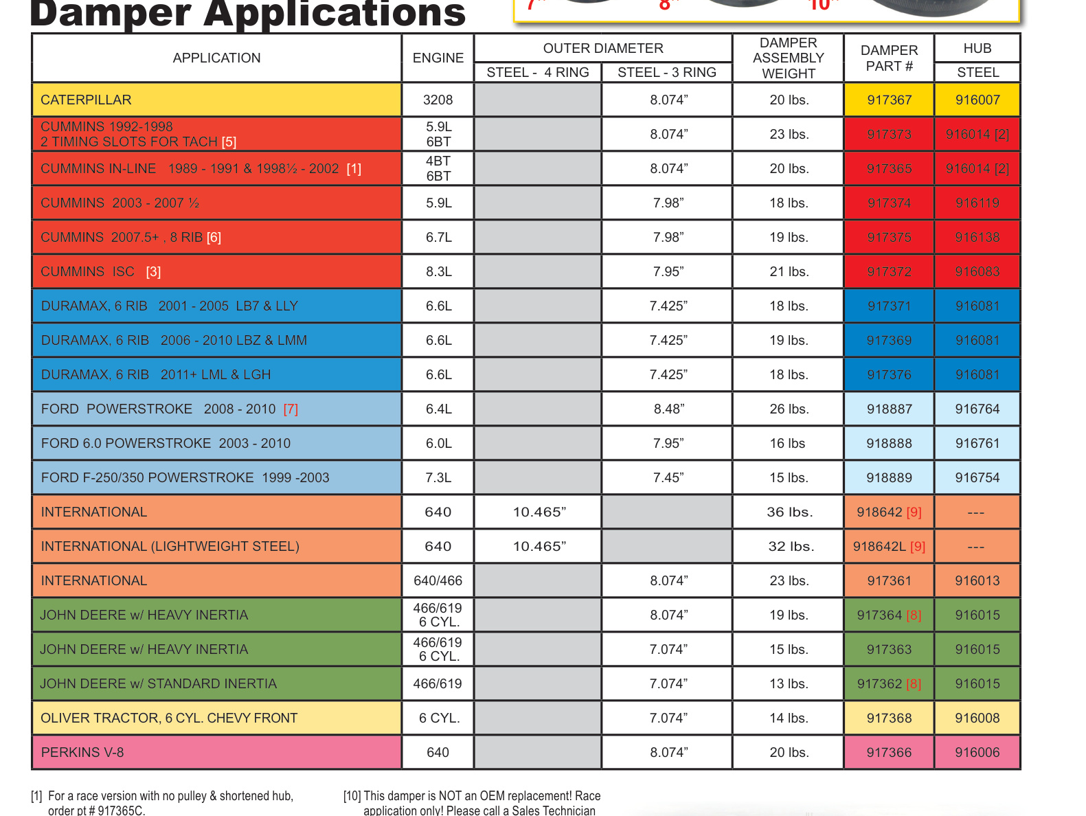
Damper Applications
Use the table below to confirm the correct damper and hub part numbers, outer diameter and assembly weight for your engine.