
Installation instructions for the BD 68RFE performance transmission for 2007-2022 RAM 6.7L Cummins pickups, offered in TorqueMaster (700HP), TowMaster (600HP) and RoadMaster builds for 2WD and 4WD. Use the part-number chart below to match your year and drivetrain.
Download the Original PDF Manual
IMPORTANT — read first: The 68RFE transmission has a unique TCM control strategy, and it is imperative the “Quick Learn” instructions are followed closely. Not following these directions correctly will void the warranty and lead to premature failure. An OEM or equivalent scan tool with a working Quick Learn function is required — if you do not have this tool, do not install this transmission.
Application & Part-Number Chart
BD 68RFE Transmission for 2007–2022 RAM Pickup with the 6.7L Cummins engine. Match your model year and drivetrain, then choose the transmission-only or transmission-plus-converter part number.
TorqueMaster Transmission (700HP)
- 07–18 2WD — Trans. only 1064262B / Trans. + converter 1064262BM
- 07–18 4WD — Trans. only 1064264B / Trans. + converter 1064264BM
- 19–22 2WD — Trans. only 1064292B / Trans. + converter 1064292BM
- 19–22 4WD — Trans. only 1064294B / Trans. + converter 1064294BM
TowMaster Transmission (600HP)
- 07–18 2WD — 1064262SS
- 07–18 4WD — 1064264SS
- 19–22 2WD — 1064292SS
- 19–22 4WD — 1064294SS
RoadMaster Transmission (500HP)
- 07–18 2WD — 1064222SS
- 07–18 4WD — 1064224SS
- 19–22 2WD — 1064302SS
- 19–22 4WD — 1064304SS
Read the instructions and warranty disclaimer before beginning installation. Special tuning is required for 2019–2022 applications for increased pressure.
Do This First
Work through these steps in order — skipping any of them may void your warranty.
- Read the transmission warranty statement (with the customer).
- Complete the top portion of the transmission warranty form.
- Ensure you have an OEM or equivalent scan tool. If you do not have this tool, do not install this transmission.
- Record the CVI’s of the stock transmission on the warranty form before performing the Quick Learn.
- Proceed with the removal and reinstallation (R&R) of the transmission — see the installation instructions below.
- Install the BD 68RFE pressure module or appropriate pressure tuning in the TCM.
- Using pressure adapter kit (1061529), record pressures on the warranty sheet.
- Proceed with the relearn procedure while continuing to update the warranty sheet.
- Fax the warranty sheet to BD Diesel and keep a copy for your records.
Introduction
BD Diesel 68RFE transmissions incorporate many upgrades and updates to improve transmission longevity and performance. See the BD website for up-to-date sales features. BD Diesel also provides YouTube walk-through videos for the transmission installation and for the Quick Learn / Drive Learn procedure — refer to those for additional detail.
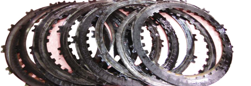
WARNING: Do not use the vehicle for heavy towing or hauling until 300 miles of stop-and-go driving has elapsed, to allow the computer to relearn the new transmission. Burnt clutches are not covered by warranty. Failure to correctly follow the relearn procedure may result in clutches that look like the photo below.
Special Tools Required
Chrysler Scanners
- WiTech — 2007–current
- Star Mobile — 2007–current
- StarScan — 2007–2009
Aftermarket Scanners
- Snap-On Modis — all years
- Auto Enginuity (with EI04 enhanced Dodge coverage) — all years
- Other scanners with FULL OE coverage (not code readers)
Other Tools
- Chrysler barring tool #7471B (for rotating the flywheel)
- Cooler-line disconnect tool, Chrysler #9546
- 300 psi oil-filled gauge with approximately 6 ft of line and a male 1/8″ NPT fitting (for applications with the line-pressure module)
- Backflow heated transmission flushing machine (for the cooler flush)
Maintenance
BD recommends the first transmission oil and filter change occur at the 3-month or 5,000 mile / 8,000 km interval. This early interval gives peace of mind and rids the transmission of any debris dislodged from the cooler. After this, OE service intervals are acceptable.
IMPORTANT: Use only MOPAR ATF+4 or an aftermarket equivalent ATF+4 transmission fluid. These are the only acceptable fluids for use in this transmission.
Aftermarket Tuners and TCMs
2007–2018 Models
- Using both the BD controller and tuning will set a P0868 fault code and may cause shift issues. Either disable line-pressure changes in your tuner when using the BD pressure controller, or do not use the BD controller if you must use tuning for line pressure.
- Other transmission tuning — for example raising the 4–5 and 5–6 shift points — will not conflict and may be run with the BD pressure module.
- Perform the drive learn with the tuner set to the power level the truck is normally used at. Do not go full throttle during shifts until the transmission has learned its CVI values.
- Changing tuner power levels forces the transmission to re-adapt shift timing, causing extra wear — avoid frequently changing power levels.
2019–2022 Models
WARNING: You must use TCM tuning to increase line pressure on these applications — do not use an inline pressure module. The factory TCM has programming flaws that become prevalent at higher line pressure: under higher load, clutches that should not be applied can pulse on. The only current fix is tuning. Contact your tuner and confirm they know of this issue and have the required workaround before installing their tuning. Suggested WOT line pressure using tuning is 250 psi.
2019+ 68RFE TCC Solenoid PI Curve Re-Learn
2019–2022 valve bodies use a Variable Force Solenoid (VFS) for the Torque Converter Clutch (TCC) with a unique close-tolerance Pressure/Inductance (PI) curve. It is necessary to update the PI data in the PCM when replacing the TCC solenoid, valve body or transmission assembly.
- BD Diesel supplies the unique code from the rectangular QR matrix as an easy-to-scan QR code with this manual. Scan it and store it safely for future reference.
- The 46- or 66-character code must be used to perform a PI Curve re-learn after installation but before the initial road test, using the “Program Torque Converter Solenoid PI Curve” routine in the scan tool.
NOTE: On the 2019+ auxiliary valve body, the rectangular QR matrix contains the PI Curve information. The separate square QR code does not contain PI Curve information.
Transmission Removal
- Disconnect the negative battery cable. Raise and support the vehicle and remove any necessary skid plates.
- Drain the transmission.
- Mark the drive shaft and axle companion flanges for assembly alignment, then remove the rear drive shaft. Remove the front drive shaft if necessary.
- Remove the exhaust support bracket from the converter housing.
- Remove the bolts securing the right power-bending bracket to the engine block and the transmission adapter plate, then remove the right-side power-bending bracket.
- Loosen the inspection cover bolts and rotate the inspection cover out of the way.
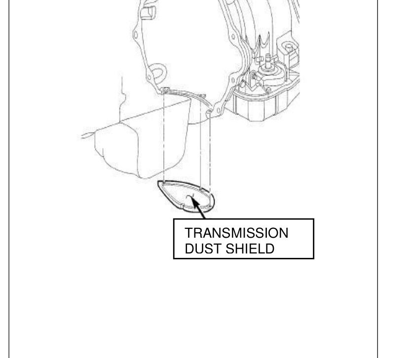
- Remove the transmission dust shield.
- Rotate the flywheel using the Chrysler barring tool #7471B (or a blade screwdriver) and remove the torque converter bolts one at a time.
- Disengage the connectors from the output speed sensor, the input speed sensor, and the transmission solenoid/TRS assembly.

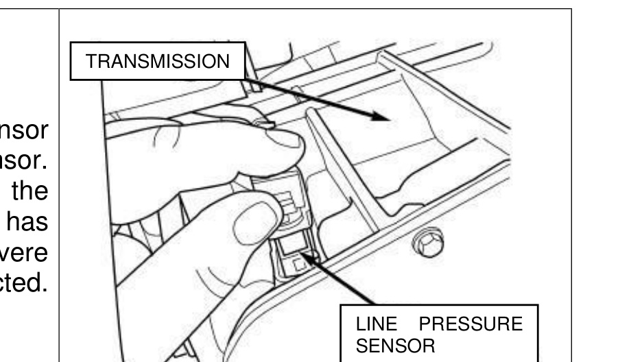
- Disengage the line pressure sensor connector from the line pressure sensor.
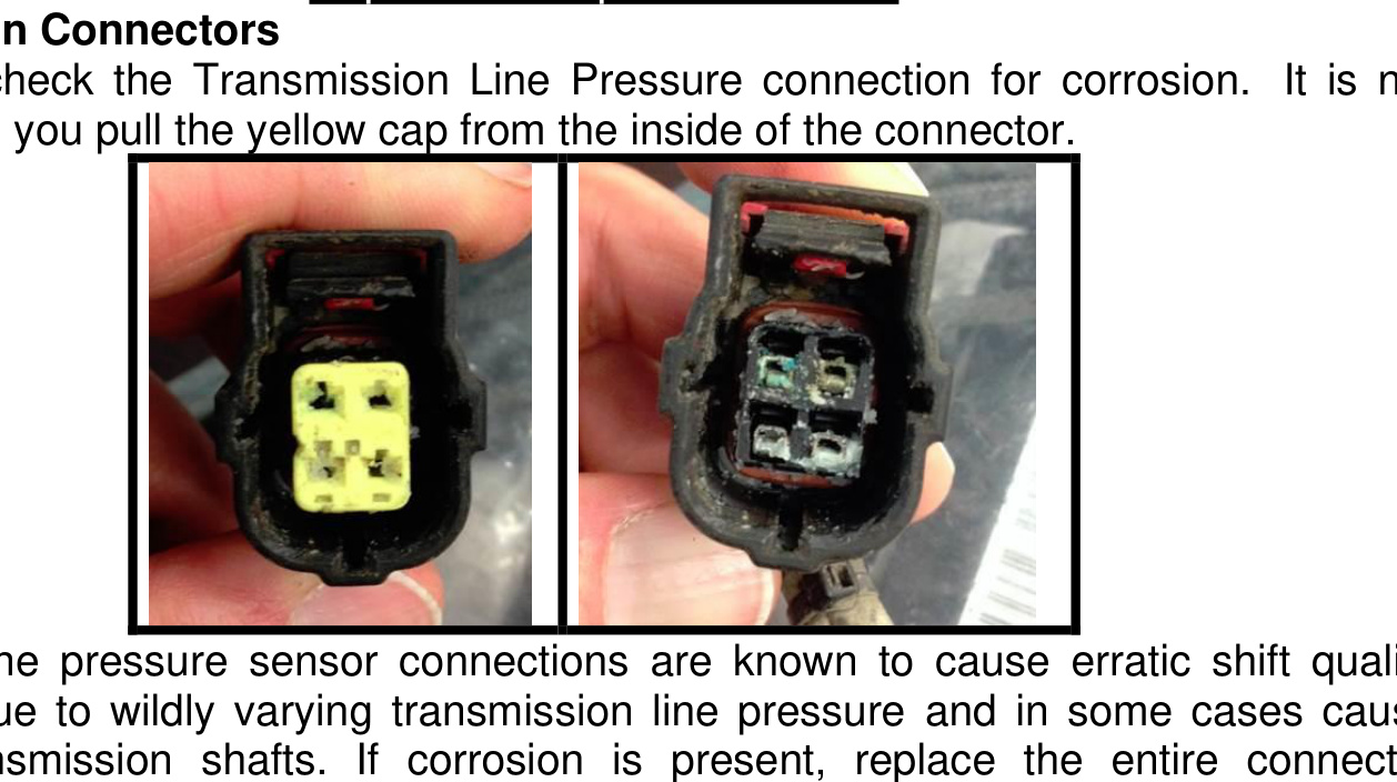
WARNING — inspect the line pressure connector for corrosion. Corrosion is not evident until you pull the yellow cap from the inside of the connector. Corroded line-pressure connections are a known issue and can cause erratic shift quality from wildly varying line pressure, and in some cases broken transmission shafts. If corrosion is present, replace the entire connector assembly.
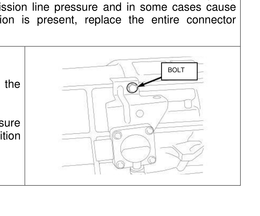
- Disconnect the electrical connector from the differential pressure sensor. Remove the bolt securing the differential pressure sensor to the transmission case and position the sensor aside.
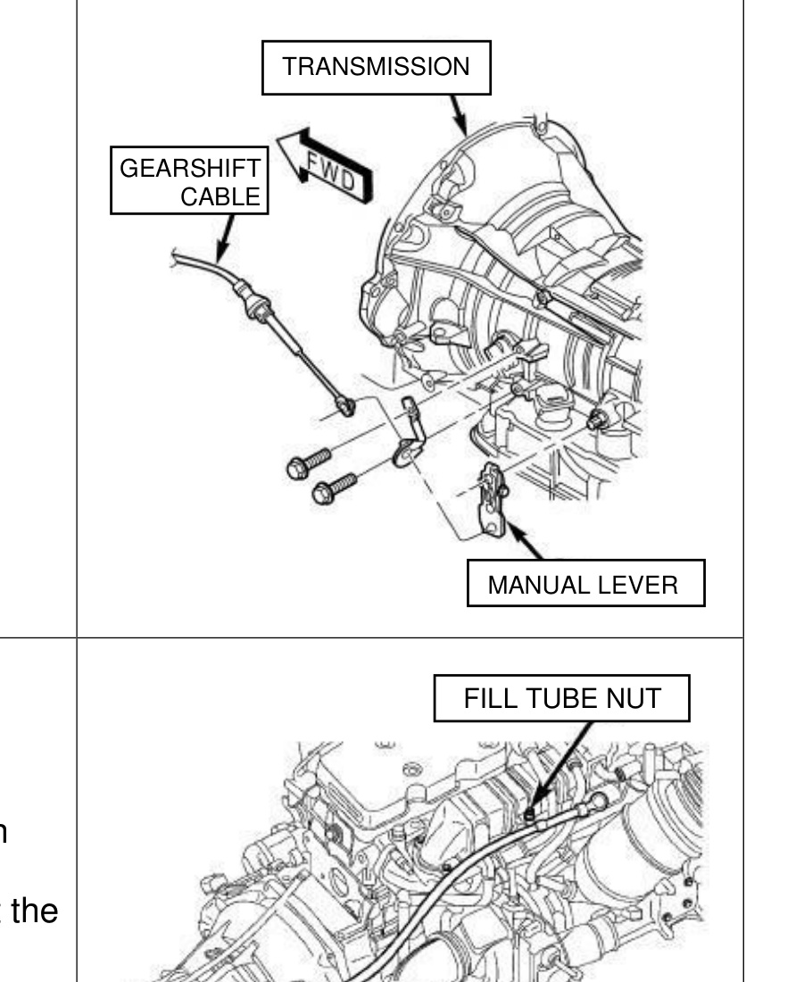
- Disconnect the gearshift cable from the transmission manual valve lever.
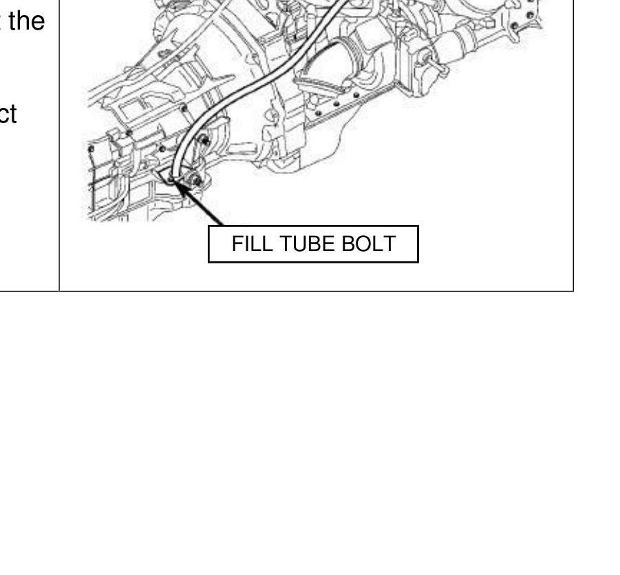
- Remove the wiring harness and position it aside. Remove the bolt securing the fill tube at the transmission. Disconnect the cooler lines from the transmission using cooler-line disconnect tool Chrysler #9546.
- Support the rear of the engine with a safety stand or jack. Raise the transmission slightly with a service jack to relieve the load on the crossmember and supports.
- Remove the wiring harness from the crossmember and position it aside. Remove the bolts securing the rear support and cushion to the transmission, then remove the crossmember from the vehicle.
- If equipped, disconnect the vent lines and connectors to the transfer case assembly, remove the transfer case mounting nuts, and remove the transfer case from the vehicle.
- Disconnect the transmission vent hose from the transmission. Remove all remaining converter-housing bolts.
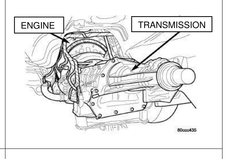
- Carefully work the transmission and torque converter assembly rearward off the engine block dowels while removing the fill tube from the fill tube bore. Hold the torque converter in place during removal. Lower the transmission and remove the assembly from under the vehicle.
Transmission Cooler Flush
WARNING: Before installing your BD transmission you must flush the transmission coolers using a backflow heated transmission flushing machine. Failure to do this may void your warranty.
If the transmission you are removing failed or has an excessive amount of debris in the pan, you should replace the transmission cooler and check valve assembly.
Torque Converter Removal
- Carefully slide the torque converter out of the old transmission and drain as much fluid as possible.
- All components and cores must be drained of fluid before being sent back to BD for core credit.
- To ship the core back, reinstall the torque converter using the special retainer plate that came on the new transmission. This prevents damage during return shipping.
Torque Converter Installation
- Ensure the brass drain plug is installed in the torque converter and preload the converter with 5 quarts of MOPAR ATF+4 (or aftermarket ATF+4). Do not use any other transmission fluid type.
- Check the converter hub and hub drive flats for sharp edges, burrs, scratches or nicks. Polish the hub and flats with 800/1000-grit paper and crocus cloth if necessary — the hub must be smooth to avoid damaging the pump seal. Verify the converter hub O-ring is properly installed and free of debris.
- Lubricate the oil pump seal lip with transmission fluid.
- Align the converter and oil pump. Carefully insert the converter into the oil pump, then rotate it back and forth until it is fully seated in the pump gears.
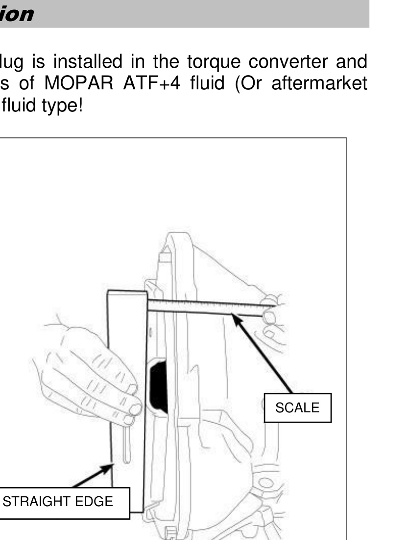
- Check converter seating with a steel scale and straightedge. The converter surface lugs should sit in front of the bell-housing face by about 25 mm (1 in.). Temporarily secure the converter with a C-clamp.
Transmission Installation
WARNING: The following items and procedures are critical to the safe operation of your transmission. Failure to follow these recommendations will result in a voided warranty.
2019–2022 Models: Before installing the transmission, safely store the 46- or 66-character PI Curve code provided with the BD transmission.
- Transfer any necessary components — such as the manual shift lever and shift cable bracket — from the original transmission onto the BD performance transmission.
- Position the transmission on the jack and secure it with chains. Check the condition of the converter drive plate and replace it if cracked, distorted or damaged (a BD flexplate is a great upgrade). Be sure the transmission dowel pins are seated in the engine block and protrude far enough to hold the transmission in alignment.
- Apply a light coating of MOPAR High Temp Grease to the torque converter hub pocket in the rear pocket of the engine’s crankshaft.
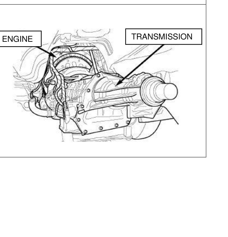
- Raise the transmission and align the torque converter with the drive plate, and the converter housing with the engine block. Move the transmission forward, then raise, lower or tilt it to align the converter housing with the engine block dowels while positioning the filler tube into the filler tube bore.
- Carefully work the transmission forward over the engine block dowels until the converter hub is seated in the crankshaft. Verify that no wires or the transmission vent hose have become trapped between the engine block and the transmission.
- Install two bolts to attach the transmission to the engine and verify the torque converter still rotates freely. Install the remaining converter-housing-to-engine bolts and tighten to 68 Nm (50 ft-lbs).
CAUTION: It is essential that the correct-length bolts are used to attach the converter to the flex plate. Bolts that are too long will damage the clutch surface inside the torque converter.
- Install the torque converter-to-drive-plate bolts and tighten to 88 Nm (65 ft-lbs). Thread locker is recommended on the torque converter bolts.
- If equipped, install the transfer case and tighten the nuts to 35 Nm (26 ft-lbs).
- Install the rear support to the transmission and tighten bolts to 47 Nm (35 ft-lbs). Install the crossmember, lower the transmission onto it, and install the mount-to-crossmember bolts. Tighten the clevis bracket-to-crossmember bolts to 47 Nm (35 ft-lbs) and the clevis bracket-to-rear-support bolt to 68 Nm (50 ft-lbs). Remove the engine support fixture.
- Install the transmission inspection cover and tighten bolts to 10 Nm (88 in-lbs). Install the right-side power-bending bracket.
- Install the transmission dust shield. Connect the gearshift cable to the transmission. Connect the wires to the solenoid and pressure-switch assembly connector.
- Connect the wires to the input speed sensor, output speed sensor and line pressure sensor. Be sure the transmission harnesses are properly routed.
NOTE: Use dielectric grease when reconnecting the line pressure sensor connector.
- Install the differential pressure sensor bolt (if equipped) and tighten to 10 Nm (88 in-lbs).
- Connect the cooler lines to the transmission. Install the transmission fill tube bolt and tighten to 10 Nm (88 in-lbs).
- Install exhaust components if necessary. Align and connect the drive shaft(s).
- Adjust the gearshift cable if necessary.
Drive Shaft Torque Specifications
- Front axle — 28 Nm (21 ft-lbs)
- Front transfer case — 88 Nm (65 ft-lbs)
- Center bearing bolts — 54 Nm (40 ft-lbs)
- Rear bolts — 115 Nm (85 ft-lbs)
Pressure Test Adapter Installation (2007–2018)
For 2007–2018 installations using the BD Line Pressure module, you must install the pressure test adapter to measure actual line pressure. This step is not used for 2019+ models or earlier models that rely on pressure tuning instead.
- Disconnect and remove the line pressure sensor.
- Install the pressure adapter with the OE sensor back into the transmission, then attach a 300 psi liquid-filled gauge to the pressure adapter.
- Route the gauge from under the vehicle into the cab, leaving sufficient clearance from the exhaust system and moving parts. Lower the vehicle.
NOTE: Transmissions that include BD’s Pressure Adapter Kit are 1064262 & 1064262B and 1064264 & 1064264B. This pressure adapter kit should remain with the vehicle for future service.
68RFE Pressure Module Installation (2007–2018 Only)
To complete the installation, install the Line Pressure Module (1030369) provided with this kit, following the instructions that come with the module kit. RoadMaster applications use module (1030366).
Fluid Fill and Check
Fill the transmission with MOPAR ATF+4 or an approved aftermarket ATF+4 equivalent.
NOTE: Fill capacities are a guide only. Correct fluid level should always be determined by the marks on the dipstick. Capacities listed are total system capacity including the torque converter and BD pan.
Fluid Capacity (2007.5–2017)
- First fill — 12 quarts (11.4 L)
- Secondary fill (includes torque converter preload) — approx. 10 quarts (9.4 L)
- Total capacity — 22 quarts (20.8 L)
Once filled, start the truck but do not drive it yet. Allow the transmission to pump fluid into the converter, coolers, etc., then re-check the fluid level.
Transmission Quick Learn
CRITICAL STEP: Connect a Chrysler or equivalent aftermarket scan tool and clear any existing transmission fault codes from the old transmission. Before beginning the Quick Learn, record the CVI values from the old transmission on your warranty sheet.
2019–2022 Models — Program PI Curve, then Quick Learn
- Select ‘Program Torque Converter PI Curve’ in the Misc Functions menu.
- Click Continue.
- Select the Valve Body / Torque Converter Solenoid option and click Continue.
- Scan and enter the 46- or 66-character PI Curve code provided on the QR label with the 2019+ transmission.
- Perform the Quick Learn by following the scan-tool instructions, then clear DTCs.
All Models — Quick Learn
STOP: Select QUICK LEARN from the special function menu. If your scan tool does not have the Quick Learn function, do not drive the vehicle — you will not be able to complete the installation.
- Follow the scan-tool instructions. The transmission will engage the various clutches to determine base CVI values and clear its adaptive learning history.
- Before driving the vehicle, record the new CVI values on your warranty sheet. The transmission is now ready for drive learning and pressure checks.
- On newer model years, look for and perform the EMCC reset/relearn to reset the learn of the torque converter.
Road Test and Pressure Checks
Before leaving for the road test, verify transmission pressures. If idle pressures are not as expected, do not test drive the vehicle — re-check the fluid level and check for fault codes or unplugged sensors, and call BD tech support for assistance.
Mainline Pressures (68RFE)
- At idle — 60–120 psi
- Wide open throttle — 250 psi
Line pressure varies with load and the operating state of the transmission. At idle in PARK with your foot off the brake, expect about 60 psi; applying the brake or shifting into gear yields approximately 120 psi.
IMPORTANT: Do not allow the vehicle to shift at full throttle when obtaining the WOT line-pressure check — it has not yet fully relearned. Instead, use the factory tap-shifter buttons to prevent shifting above 4th gear. Lightly accelerate until in fourth and in lockup, then accelerate to WOT in this gear to get a pressure reading.
Drive Learn Procedure
- Accelerate with the minimum throttle required when leaving the shop and get onto a quiet stretch of road.
- Slowly accelerate the vehicle from first gear up to fourth gear. Repeat a few times until shift quality becomes consistent, then increase throttle slightly and repeat.
- As shift quality improves, allow the truck to shift into 5th and 6th gears. Generally, if gears 1–4 are correctly learned, 5th and 6th will shift nicely because they use the same clutches as 2nd and 3rd.
- Complete a series of N-to-D and N-to-R shifts and verify shift quality is acceptable. See the Detailed Relearn Information below to target specific shifts.
Final Check and Gauge Removal
- After the drive learn and pressure checks are complete, bring the truck back into the shop and remove the transmission pressure gauge adapter.
- Use the scan tool to view CVI values and record them on the warranty sheet. Record the pressure readings from the gauge or scan tool as appropriate.
- Verify the fluid level now that it is hot and top up if required.
Returning the Vehicle to the Customer
WARNING: Inform the customer the truck must not be used for heavy towing or hauling until 300 miles of stop-and-go driving has been completed, so the TCM has time to adjust shift timing correctly.
Review the warranty statement with the customer if not done previously, and ensure they are aware of the 5,000 mile / 8,000 km first fluid change requirement.
Detailed Relearn Information
You must perform a transmission Quick Learn so the TCM can recalibrate to the new CVI indexes. This requires an OE-level scan tool. The Quick Learn / Drive Learn procedure must be performed if any of the following repairs are applied:
- Transmission replacement
- Transmission Control Module (TCM) replacement
- Solenoid pack replacement
- Clutch plate and/or seal replacement
- Valve body replacement or recondition
- Torque converter replacement
- Battery disconnect or replacement
- Power upgrade or flash programmer installation and/or updates
A relearn may also be required due to a faulty electrical connection or a sensor failure.
68RFE Transmission Learn Procedure
Once the transmission is installed and full of fluid, connect a scan tool.
- Locate the TCM or ECM Reset and complete the test.
- Locate the Clutch Fill Volume Index (CVI) values in the data section of the TCM (this data is in the PCM on 2010–12 models). Record these values on the data sheet provided.
- Perform a Quick Learn (located in the MISC section of the TCM/PCM). After it completes, record the CVI values again.
- Begin the initial test drive. Do not accelerate aggressively. Bring the vehicle to normal operating temperature and find a long, level stretch of road with little to no traffic.
- Bring the vehicle to a complete stop, place the transmission in reverse for 2–3 seconds, then back into drive. Watching throttle percentage, accelerate holding a 15-degree throttle angle through the 1-2, 2-3 and 3-4 upshifts, then bring the vehicle back to a stop.
- Repeat the acceleration and upshift procedure at least 2–4 times before the next reverse or park selection. Repeat until the CVI values stabilize (stop changing during shifts).
- Once CVIs are stable, accelerate from a stop at a 30-degree throttle angle through all gears to verify quick, clean shifts. If any stumble, chatter or clunking is felt, repeat the initial drive learn to re-stabilize the CVIs.
- When upshifts feel quick and crisp, gradually accelerate at higher throttle percentages through all gears until 50–60% throttle is reached. If upshifts become irregular at any time, repeat the initial drive learn.
After the drive learn is complete and the transmission shifts correctly, record a final set of CVI values on the data sheet. Any particularly objectionable shifts can be fine-tuned using the targeted procedures below.
NOTE: It is not necessary to perform the complete Drive Learn every time the TCM is Quick Learned — perform only the portions that target the objectionable shift.
Learn a Smooth 1st Neutral-to-Drive Shift
Perform only if the complaint is a delayed or harsh shift the first time the transmission is put into gear after sitting with the engine off for at least 10 minutes.
NOTE: The transmission oil temperature must be 80–110°F (27–43°C). Start the engine only after the engine and ignition have been off for at least ten minutes.
With the vehicle stopped and the service brake applied, record the 1st N-D UD CVI while performing a Neutral-to-Drive shift. The 1st N-D UD CVI accounts for air entrapment in the UD clutch after the engine has been off. Repeat until the value stabilizes. If this takes too long for the allowed temperature window, the vehicle may be returned to the customer with an explanation that the shift will improve daily during normal use.
Learn a Smooth Neutral-to-Drive Garage Shift
Perform if the complaint is a delayed or harsh shift after the vehicle has had its first shift.
NOTE: Best learned at 80–110°F (27–43°C), though additional learning occurs from 0°F to 200°F.
Start the engine and shift to drive. Move the vehicle to at least 10 MPH (16 km/h) and come to a stop to ensure no air is present in the UD circuit. Perform repeated N-D shifts at a stop, pausing in Neutral for 2–3 seconds, and monitor the Norm N-D UD CVI until the value stabilizes and the N-D shifts become smooth.
Learn the 1st 3-4 Shift After a Restart or Shift to Reverse
NOTE: The transmission oil temperature must be above 80°F (27°C).
With the engine running, select reverse for over 2 seconds. Shift to Drive and accelerate from a stop at a steady 15-degree throttle, performing a 3-4 shift while noting the 1st 3-4 OD CVI. Repeat until the 1st 3-4 upshift becomes smooth and the CVI stabilizes.
Learn a Smooth 3-4 and 4-5 Upshift
NOTE: The transmission oil temperature must be above 110°F (43°C).
Accelerate from a stop at a steady 15-degree throttle and perform multiple 1-2, 2-3, 3-4 and 4-5 upshifts. Repeat until the 3-4 and 4-5 shifts become smooth and the OD and 4C CVIs become stable.
Learn a Smooth 5-4 Coastdown and Part-Throttle 5-4 Kickdown
NOTE: The transmission oil temperature must be above 110°F (43°C).
At 40–60 MPH (64–97 km/h), perform repeated 5-4 kickdown shifts until the UD volume becomes stable and the shift becomes smooth.
Learn a Smooth 1-2 Upshift and 3-2 Kickdown
NOTE: The transmission oil temperature must be above 110°F (43°C).
With a vehicle speed below 30 MPH (48 km/h) and the transmission in 3rd gear, perform multiple 3-2 kickdowns until they become smooth and the 2C CVI becomes stable.
Learn a Smooth Manual 2-1 Pulldown Shift
NOTE: The transmission oil temperature must be above 110°F (43°C).
At around 25–30 MPH (40–48 km/h) in Manual 2nd, perform manual pulldowns to Low or 1st gear at closed throttle. Repeat until the LR CVI becomes stable and the manual 2-1 becomes smooth.
Learn a Smooth Neutral-to-Reverse Shift
NOTE: The transmission oil temperature must be above 110°F (43°C).
With the vehicle stopped, perform Neutral-to-Reverse shifts until smooth. An unlearned N-R shift may be harsh or exhibit a double bump. If shifts remain rough after the clutch volume stabilizes, an internal transmission problem may be present.
Learn a Smooth 5-6 Upshift
NOTE: The transmission oil temperature must be above 110°F (43°C).
Accelerate through 55 MPH (88 km/h) at a steady 10–15 degree throttle and perform multiple 5-6 upshifts. Repeat until the 5-6 shift becomes smooth and the Alt 2C CVI becomes stable. A separate 2C volume (2CA) is used and learned for 5-6 shifts, independent of the 2C CVI learned on 3-2 kickdowns.
Solenoid Pack Field Replacement
IMPORTANT: BD Diesel transmissions use a different solenoid pack than stock for 2011–2018 vehicles. You must use the 2008–2010 universal solenoid pack (Chrysler part #68353383AB), identified by the white connector — not the “correct” solenoid pack for your vehicle.
Your transmission may have come with a gray solenoid pack connector that has been painted white. These have been modified by BD to be functionally equivalent to the white solenoid packs.
2019–2022 Models: If replacing the valve body, solenoid pack or TCC solenoid, scan and save the new TCC solenoid’s PI Curve information from the QR code matrix on the solenoid and enter it into the scan tool’s ‘Program Torque Converter Solenoid PI Curve’ routine (Misc functions menu) to update the PCM. Also remove the old TCC solenoid’s QR code stickers if present on the transmission body.
Troubleshooting
P0868 Low Line Pressure Fault Code
Code present at idle:
- Indicates a pressure module issue or connection issue.
- Temporarily remove the BD pressure box, clear the code and retest. With the module removed, the truck should run stock pressures.
Code present at WOT:
- Possible connector issue or module issue.
- If no connector problems are found, attach a mechanical gauge and compare scan-tool pressure to the mechanical gauge at WOT. If pressure is below 230 psi, the transmission cooler is likely causing reduced flow. If replacing the cooler does not remedy this, contact BD.
P0871 Transmission Fluid Pressure Fault Code
Code present after solenoid pack replacement:
- BD transmissions use a different solenoid pack than stock for 2011–2018 vehicles. You must use the 2008–2010 universal solenoid pack (Chrysler part #68353383AB) identified by the white connector, not the “correct” pack for your vehicle.
Transmission Cooler Check
Disconnect the cooler line and verify the cooler flow rate — at idle it should be a minimum of 1.5 GPM (drain into a clean bucket for this test). If it does not meet the requirement, replace your cooler and check valve assembly.