
Installation manual for the BD 68RFE valve body, part #1030465, for 2008–2018 Ram 6.7L Cummins (white, grey and solenoid variants noted in the guide). It can be run on its own, with an aftermarket pressure controller, or with TCM tuning. Does not fit 2019+ blue-connector models.
Download the Original PDF Manual
IMPORTANT: Please read all instructions before installation. This valve body fits the following BD kits: 1030465 (2008–2011 w/o solenoid, white), 1030467 (2008–2018 w/ solenoid), and 1030468 (2012–2018 w/o solenoid, grey). It does not fit 2019+ trucks with the blue connector.
Aftermarket Tuners or TCMs
You can use this valve body on its own, with an aftermarket pressure controller, or with TCM tuning.
NOTE: It is not recommended to combine TCM tuning that increases mainline pressure with a pressure controller, as this may cause shift issues and set a P0868 fault code.
Summary of Upgrades
This performance valve body includes a number of upgrades:
- Hard-anodized aluminum accumulator pistons with dual seals
- Thicker accumulator plate
- Separator plate with bonded gasket
- Replacement clutch feed seals
- Steel insert for the solenoid switch valve with oversized end plugs
Kit Contents
Please check that you have all the parts listed for your kit before beginning.
- Kit 1030465 — Gasket (16001523) ×1; Valve Body w/o Solenoid (1300465-6) ×1
- Kit 1030467 — Gasket (16001523) ×1; Valve Body w/ Solenoid (1300465-1) ×1
- Kit 1030468 — Gasket (16001523) ×1; Valve Body w/o Solenoid (1300465-5) ×1
Tools Required
- Drain pan
- Transmission funnel
- 8mm socket
- T25 Torx socket
- Torque wrench (in-lbs)
- Brake clean or parts cleaner
- Scraper
Upgrade Options
- 1030240 — Torque Converter
- 1061525 — 6.7L HD Transmission Pan
- 1041220 — 6.7L Cummins Flex Plate
- 1061529 — Adapter Tool, 68RFE
- 1030369 — Transmission Pressure Controller
IMPORTANT — Quick Learn is mandatory. The 68RFE transmission has a unique TCM control strategy, and the “Quick Learn” instructions must be followed closely. Not following these directions correctly will void the warranty and lead to premature failure. Do not use the vehicle for heavy towing or hauling until 300 miles of stop-and-go driving has elapsed to allow the computer to relearn the new valve body.
Installation
Drain and Disconnect
- Ensure all kit components are accounted for before installation.
- Disconnect the vehicle batteries and secure the cables away from the batteries.
- Lift the transmission dipstick approx. 6 inches to avoid interference later on.
- Raise the vehicle on a lift. If using a jack, use safety stands and chock the wheels.
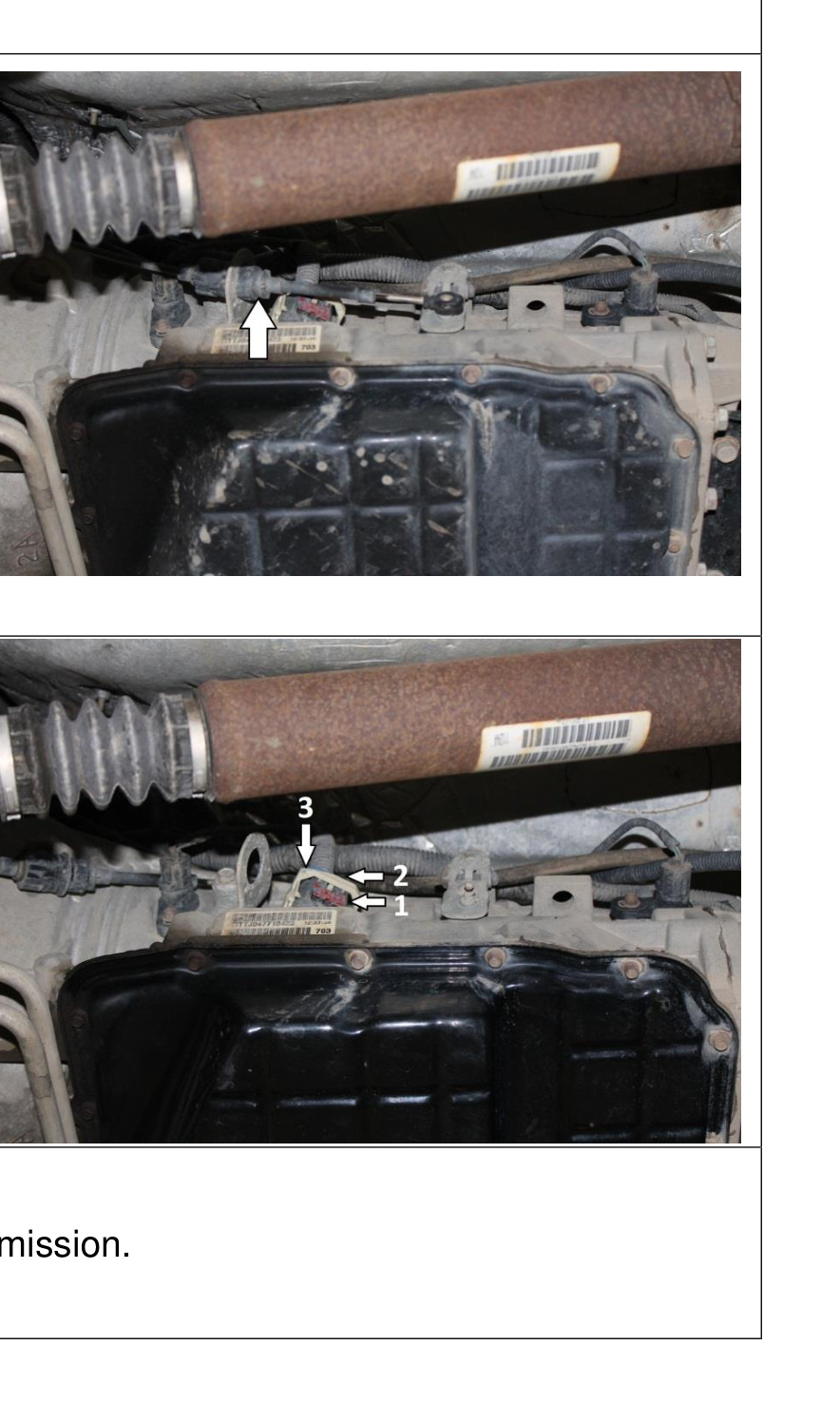
- Remove the shifter cable from the transmission for better access to the main electrical connector.
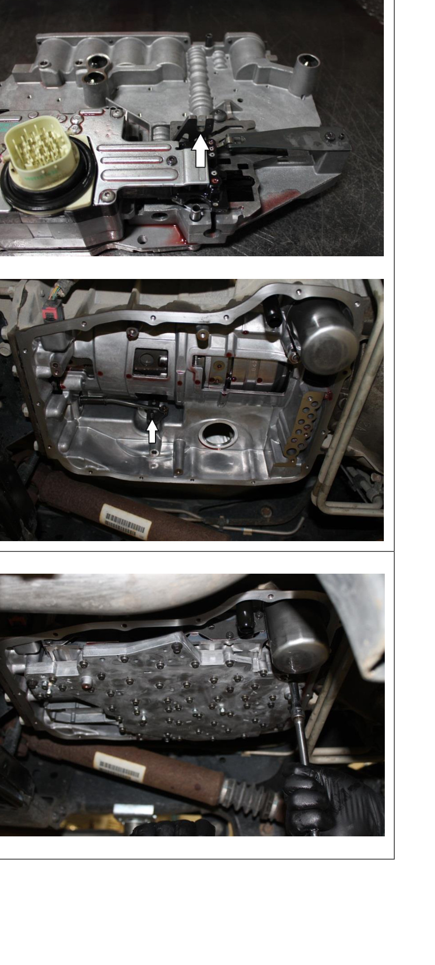
- To remove the connector, push the red tab (1) downward. Then press the black tab (2), which allows the white handle (3) to be rotated downward, releasing the connector from the transmission.
- Position a drain pan below the transmission.
Drop the Pan and Remove the Valve Body
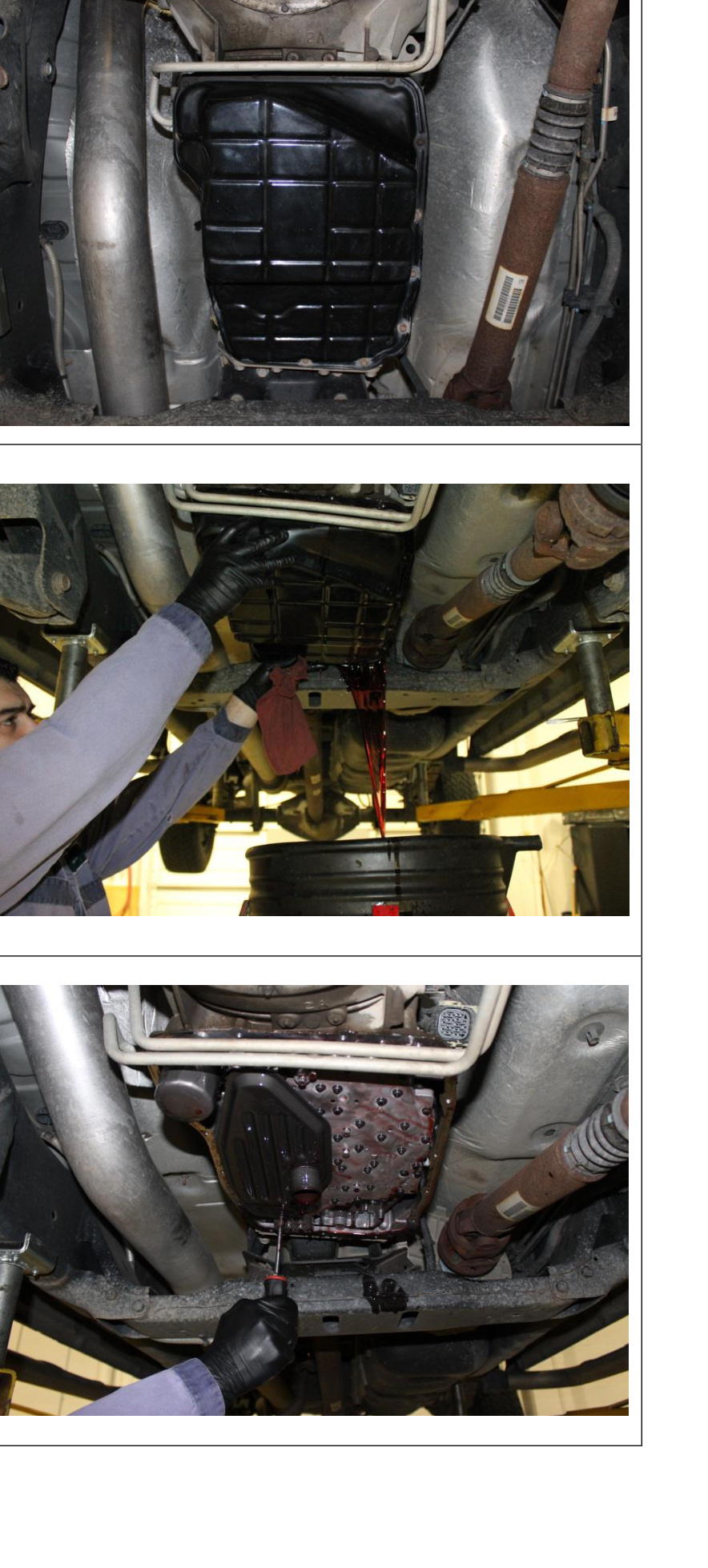
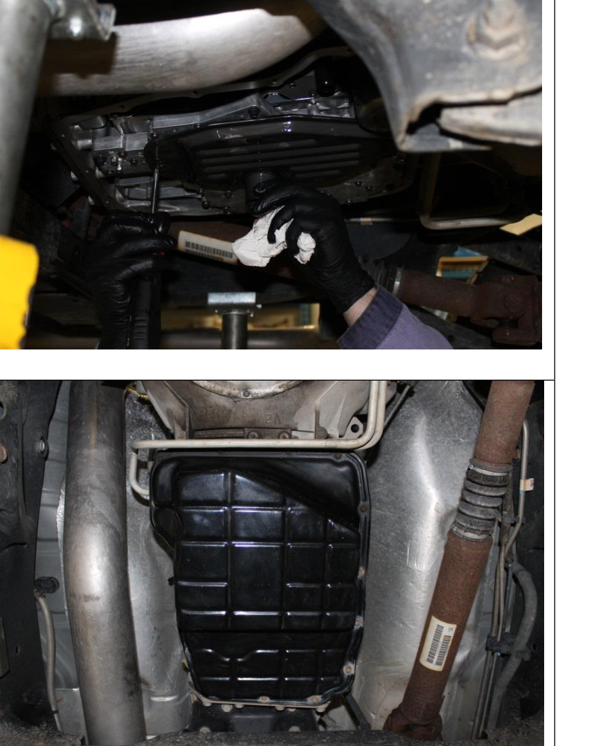
- Remove 14 of the 15 transmission pan bolts (8mm). Loosen the remaining bolt but leave it in place to keep the pan from falling. The transmission cooler lines may need to be moved to access some bolts — gently pry them out of the way.
- Tap the pan with a mallet to break the silicone gasket seal. Allow the fluid to drain. Remove the last screw and drain the remainder of the fluid.
- Remove the transmission filter by removing the one T25 Torx screw.
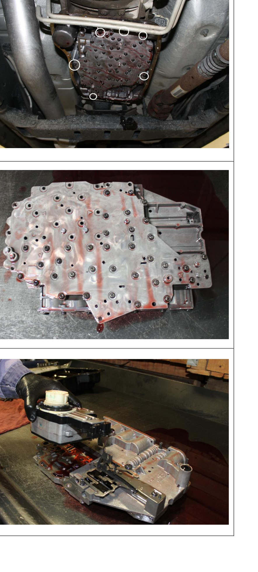
- Remove the six 8mm bolts securing the valve body to the transmission. Drain the valve body of fluid. To remove the valve body, wiggle it while pulling downward to work the electrical connector through the case.
- Place the valve body on a clean work surface.
- For kits 1030465/1030468 (w/o solenoid), remove the fifteen T25 Torx screws securing the solenoid pack to the valve body, remove the solenoid pack and set it aside.
NOTE: All bolts are the same length.
Transfer the Solenoid Pack to the New Valve Body
- For kits 1030465/1030468, install the previously removed solenoid pack onto the new valve body. Be sure to properly align the pin on the solenoid pack with the slot on the valve body. Due to the alignment dowels, the valve body may need to be wiggled down into position. Install the solenoid pack attaching screws, then install the remaining Torx screws to fasten the solenoid pack to the valve body.
IMPORTANT: On rare occasions, the solenoid pack gasket comes with a small nub on one side. This nub must be removed using a file or blade before installation, as the new plate blocks off the opening (it is not present on most applications).
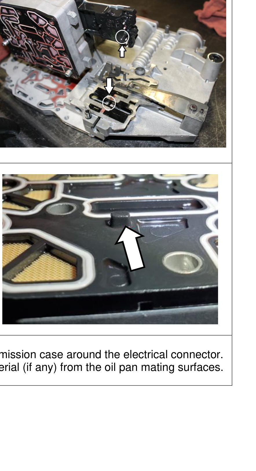
- Wipe clean the bore on the transmission case around the electrical connector. Scrape all old silicone gasket material (if any) from the oil pan mating surfaces.
Reinstall the Valve Body, Filter and Pan
- Check that the shift lever on the valve body lines up with the shift lever on the transmission, then lift the valve body back into the transmission. Start the 8mm screws by hand — do not tighten yet. Work the shift lever on the outside of the transmission case by hand to ensure the lever is making contact with the valve body correctly.
IMPORTANT: Use great care when reinstalling the valve body — the gasket that mates with the front of the case must line up correctly. Do not fold or pinch it during installation.
- Torque the valve body attaching bolts to 105 in-lbs.
- If desired, install new filter(s). Otherwise, reinstall the filter/pickup assembly. Torque to 50 in-lbs.
- Place the supplied gasket on the transmission pan. Hold the pan below the transmission and install the attaching screws. Torque the pan screws to 105 in-lbs.
- Re-attach the transmission main electrical connector. Reattach the shifter cable to the shift lever.
- Lower the vehicle.
- Reconnect the vehicle batteries.
- Fill with transmission fluid until the COLD line is met. Start and run the vehicle. Move the shifter through the different gears twice to fill the valve body. Check for leaks. Check the fluid level again and top up as required.
Torque Specifications
- Valve body attaching bolts — 105 in-lbs
- Filter / pickup assembly — 50 in-lbs
- Transmission pan screws — 105 in-lbs
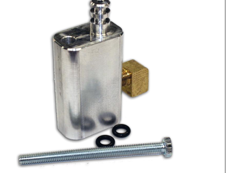
Verifying Line Pressure (Optional)
If you would like to verify the increases in line pressure, use adapter kit BD #1061529 in conjunction with a 300 psi gauge. Pressures at wide open throttle should be between 240–260 PSI with a mechanical gauge.
Transmission Quick Learn
For a detailed walkthrough, see the BD Quick Learn and Drive Learn video on YouTube.
CRITICAL STEP! Connect a Chrysler or equivalent aftermarket scan tool to the vehicle and clear any existing transmission fault codes. Select QUICK LEARN from the special function menu. If your scan tool does not have the QUICK LEARN function, STOP — do not drive the vehicle. You will not be able to complete the installation.
- Follow the instructions on the scan tool. The transmission will engage the various clutches to determine base CVI values and will clear its adaptive learning history.
- On newer model years, look for and perform the EMCC reset/relearn. This resets the learn of the torque converter.
Road Test and Pressure Checks
WARNING: Before leaving for the road test, verify transmission pressures. If idle pressures are not as expected, DO NOT TEST DRIVE THE VEHICLE. Re-check the fluid level, and check for fault codes or unplugged sensors. Call BD tech support for assistance.
Mainline pressures (68RFE):
- At idle — 60–120 psi
- Wide open throttle — ~250 psi
Line pressure varies with load and the operating state of the transmission. At idle in PARK with your foot off the brake, 60 psi is expected; applying the brake or shifting into gear yields approximately 120 psi.
NOTE: Do not allow the vehicle to shift at full throttle when obtaining the WOT line-pressure check — it will not yet be fully relearned. Instead, use the factory tap-shifter buttons to prevent shifting above 4th gear. Lightly accelerate until in fourth and in lockup, then accelerate to WOT in that gear to get a reading.
Drive Learn Procedure
- Accelerate with the minimum throttle required when leaving the shop and get onto a quiet stretch of road.
- Slowly accelerate the vehicle from first gear up to fourth gear.
- Repeat this process a few times until the shift quality becomes consistent. Increase throttle slightly and repeat.
- As shift quality improves, allow the truck to shift into 5th and 6th gears as well. Generally, if gears 1–4 are correctly learned, 5th and 6th will shift nicely since they use the same clutches as 2nd and 3rd.
- Complete a series of N→D and N→R shifts and verify shift quality is acceptable. See the detailed drive-learn information below to target specific shifts.
Final Check and Gauge Removal
- After the drive learn and pressure checks are complete, bring the truck back into the shop.
- Verify the fluid level now that it is hot and top up if required.
Returning the vehicle to the customer: The customer must be informed that the truck is not to be used for heavy towing or hauling until 300 miles of stop-and-go driving has been completed, so that the TCM has time to adjust shift timing correctly.
Detailed Relearn Information
You must perform a transmission Quick Learn so the TCM can recalibrate to the new CVI indexes. This requires an OE-level scan tool. The Quick Learn / Drive Learn procedure must be performed whenever any of the following repairs are applied to the vehicle:
- Transmission replacement
- Transmission Control Module (TCM) replacement
- Solenoid pack replacement
- Clutch plate and/or seal replacement
- Valve body replacement or recondition
- Torque converter replacement
- Battery disconnect or replacement
- Power upgrade or flash programmer installation and/or updates
A relearn may also be triggered by a faulty electrical connection or a sensor failure.
68RFE Transmission Learn Procedure
Once the transmission is installed and full of fluid, connect a scan tool. First, locate the TCM or ECM Reset and complete the test. Next, locate the Clutch Fill Volume Index (CVI) values in the data section of the TCM (this data is in the PCM on 2010–12 models). Record these values on the data sheet provided. Then perform a Quick Learn, located in the MISC section of the TCM or PCM. After the Quick Learn completes, record the CVI values again.
Now you are ready for the initial test drive. It is imperative not to accelerate aggressively on this drive. Bring the vehicle up to normal operating temperature and find a long, level stretch of road with little to no traffic. To initiate the first part of the drive learn, bring the vehicle to a complete stop, place the transmission into reverse for 2–3 seconds, then back into drive. Watching throttle percentage, accelerate holding a 15-degree throttle angle through the 1-2, 2-3 and 3-4 upshifts, then bring the vehicle back to a stop. Repeat the acceleration and upshift procedure at least 2–4 times before the next reverse or park selection. Repeat the complete procedure until the CVI values stabilize (stop changing during shifts).
Once the CVI values have stabilized, the drive learn is ready for heavier-throttle upshifts. Accelerate from a stop at a 30-degree throttle angle through all gears to verify quick, clean shifts. If any stumble, chatter or clunking is felt, repeat the initial drive-learn test to re-stabilize the CVI values. When upshifts feel quick and crisp, accelerate at a higher and higher throttle percentage through all gears until 50–60% throttle is reached. If the upshifts become irregular at any time, repeat the initial drive-learn procedure.
After the drive learn is complete and the transmission is shifting correctly, record a final set of CVI values on the data sheet. Any particularly objectionable shifts can be fine-tuned by following the applicable procedure below. At this time the vehicle can be released to the customer to complete the break-in period.
NOTE: It is not necessary to perform the complete Drive Learn every time the TCM is Quick Learned. Perform only the portions that target the objectionable shift.
Learn a Smooth 1st Neutral-to-Drive Shift
Perform this only if the complaint is a delayed or harsh shift the first time the transmission is put into gear after the vehicle sits with the engine off for at least 10 minutes. This teaches the TCM the 1st N-D UD CVI.
NOTE: The transmission oil temperature must be between 80–110°F (27–43°C). Start the engine only when the engine and ignition have been off for at least ten (10) minutes.
- With the vehicle at a stop and the service brake applied, record the 1st N-D UD CVI while performing a Neutral-to-Drive shift. This CVI accounts for air entrapment in the UD clutch that may occur after the engine has been off for a period of time.
- Repeat until the recorded 1st N-D UD CVI value stabilizes.
NOTE: If this procedure takes too long to complete within the allowed oil-temperature window, the vehicle may be returned to the customer with an explanation that the shift will improve daily during normal use. The TCM also learns at higher oil temperatures, but those values are not viewable on the scan tool.
Learn a Smooth Neutral-to-Drive Garage Shift
Perform this if the complaint is a delayed or harsh shift when the transmission is put into gear after its first shift. This teaches the Norm N-D UD CVI.
NOTE: Oil temperature must be between 80–110°F (27–43°C) to learn the UD CVI. Additional learning occurs from as low as 0°F to as high as 200°F. This may be performed at any temperature that experiences poor shift quality; although the UD CVI may not change, shift quality should improve.
- Start the engine and shift to Drive. Move the vehicle forward to at least 16 km/h (10 MPH) and come to a stop. This ensures no air is present in the UD hydraulic circuit.
- Perform repeated N-D shifts at a stop, pausing in Neutral for at least 2–3 seconds, and monitor the Norm N-D UD CVI volume until the value stabilizes. The value will change during the N-D shift — this is normal, since the UD value differs for the N-D shift versus the normal value used for 4-3 coastdown and kickdowns. Repeat until the Norm N-D UD CVI stabilizes and the N-D shifts become smooth.
Learn the 1st 3-4 Shift After a Restart or Shift to Reverse
NOTE: The transmission oil temperature must be above 80°F (27°C).
- With the engine running, select reverse gear for over 2 seconds.
- Shift to Drive and accelerate from a stop at a steady 15-degree throttle opening, performing a 3-4 shift while noting the 1st 3-4 OD CVI.
- Repeat until the 1st 3-4 upshift becomes smooth and the 1st 3-4 OD CVI stabilizes.
Learn a Smooth 3-4 and 4-5 Upshift
NOTE: The transmission oil temperature must be above 110°F (43°C).
- Accelerate from a stop at a steady 15-degree throttle opening and perform multiple 1-2, 2-3, 3-4 and 4-5 upshifts. The 2nd 3-4 shift following a restart or shift to reverse will be shown as a value between the 1st 3-4 OD CVI and the normal OD CVI. Updates to the normal OD CVI occur after the 2nd shift into 4th gear following a restart or shift to reverse.
- Repeat until the 3-4 and 4-5 shifts become smooth and the OD and 4C CVI become stable.
Learn a Smooth 5-4 Coastdown and Part-Throttle 5-4 Kickdown
NOTE: The transmission oil temperature must be above 110°F (43°C).
- At a vehicle speed between 64–97 km/h (40–60 MPH), perform repeated 5-4 kickdown shifts.
- Repeat until the UD volume becomes somewhat stable and the shift becomes smooth.
Learn a Smooth 1-2 Upshift and 3-2 Kickdown
NOTE: The transmission oil temperature must be above 110°F (43°C).
- With a vehicle speed below 48 km/h (30 MPH) and the transmission in 3rd gear, perform multiple 3-2 kickdowns.
- Repeat until the 3-2 kickdowns become smooth and the 2C CVI becomes stable.
Learn a Smooth Manual 2-1 Pulldown Shift
NOTE: The transmission oil temperature must be above 110°F (43°C).
- With the vehicle speed around 40–48 km/h (25–30 MPH) in Manual 2nd, perform manual pulldowns to Low or 1st gear at closed throttle.
- Repeat until the LR CVI becomes stable and the manual 2-1 becomes smooth.
Learn a Smooth Neutral-to-Reverse Shift
NOTE: The transmission oil temperature must be above 110°F (43°C).
- With the vehicle at a stop, perform Neutral-to-Reverse shifts until the shift is smooth. An unlearned Neutral-to-Reverse shift may be harsh or exhibit a double bump.
If any of the shifts are still not smooth after the clutch volume stabilizes, an internal transmission problem may be present.
Learn a Smooth 5-6 Upshift
NOTE: The transmission oil temperature must be above 110°F (43°C).
- Accelerate the vehicle through 88 km/h (55 MPH) at a steady 10–15-degree throttle opening and perform multiple 5-6 upshifts.
- Repeat until the 5-6 shift becomes smooth and the Alt 2C CVI becomes stable. There is a separate 2C volume (2CA) used and learned for 5-6 shifts; it is independent of the 2C CVI learned on 3-2 kickdowns.
Solenoid Pack Field Replacement
If you must replace your valve body solenoid pack, be aware that BD Diesel valve bodies (with included solenoid packs) use a different solenoid pack than stock valve bodies for 2011–2018 vehicles.
- If your BD valve body came with a solenoid pack, you must use the 2008–2010 universal solenoid pack (Chrysler part #68353383AB) identified by the white connector — not the “correct” solenoid pack for your vehicle.
- If your BD valve body did not come with a solenoid pack, use the “correct” solenoid pack for your vehicle.
- Your valve body may have come with a grey solenoid-pack connector that has been painted white. These have been modified by BD to be functionally equivalent to the white solenoid packs.
Troubleshooting
P0869 — Low Line Pressure Fault Code
Code present at idle:
- Indicates a pressure-module issue or a connection issue.
- If using a pressure enhancer (e.g., BD part #1600368), clear the code and retest to confirm whether it is a pressure-enhancer issue. With the module removed, the truck should run stock pressures.
Code present at WOT:
- Possible connector issue or module issue.
- If no problems are found with the connector, attach a mechanical gauge and compare the scan-tool pressure to the mechanical gauge at WOT. If pressure is below 230 psi, there is likely an issue with the transmission cooler causing reduced flow. If replacing the cooler does not remedy this, call BD.
P0871 — Transmission Fluid Pressure Fault Code
Code present after solenoid pack replacement:
- BD Diesel valve bodies use a different solenoid pack than stock valve bodies for 2011–2018 vehicles. If your valve body came with a solenoid pack, you must use the 2008–2010 universal solenoid pack (Chrysler part #68353383AB) identified by the white connector — not the “correct” solenoid pack for your vehicle.
Transmission Cooler Check
Disconnect the cooler line and verify the cooler flow rate. At idle it should be a minimum of 1.5 GPM (you can drain into a clean bucket for this test). If it does not meet the requirement, you will need to replace your cooler and check-valve assembly.