
Installation instructions for the BD Allison 1000 performance transmission for 2000-2005 Duramax trucks (LB7 and LLY, 2WD and 4WD). Read the warnings before starting and never use water-based flushing fluid. This guide covers removal, fluid requirements and complete installation.
Download the Original PDF Manual
WARNING — Do NOT use water-based transmission flushing fluid. The lining in the converter clutches will disintegrate, rendering the converter useless and the warranty will be voided.
IMPORTANT: Please read the instructions and disclaimer completely before beginning installation.
Applications
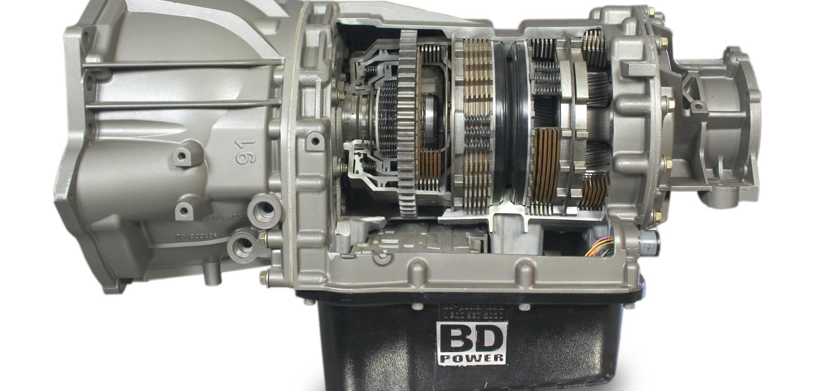
This BD performance Allison 1000 transmission fits the following 2000-2005 Duramax models:
- 2WD: 1064702 — 2000-2003 LB7 (Allison 1000)
- 2WD: 1064722 — 2004-2005 LLY (Allison 1000)
- 4WD: 1064704 — 2000-2003 LB7 (Allison 1000)
- 4WD: 1064724 — 2004-2005 LLY (Allison 1000)
Removal
- Park the vehicle, apply the park brake, and open the hood.
- Record your sound system and clock preset settings (if desired) and disconnect both negative cables on the batteries.
- Remove the transmission dipstick.
- With the vehicle safely supported on an overhead hoist, remove the transmission pan drain plug and drain the fluid.
- Remove both front skid plates for easy access to components.
- Remove both bolts (15mm hex socket or wrench) holding the starter in place and, with rope or wire, secure the starter up and out of the way on the frame. This allows access to the torque converter / flex plate bolts through the starter opening.
NOTE: The starter wires do not have to be disconnected to perform this operation.
- Torque Converter (TC) removal procedure:
- Locate the transmission / bell housing window at the lower left corner.
- View the converter and flex drive plate through this window.
- Use a 1½″ box-end wrench on the crankshaft front damper bolt to turn the crankshaft until the flex plate holes come into view through the window from below. This indicates a removal point.
- Shine a flashlight through the right-side frame and suspension members to locate the converter mounting bolts through the starter mounting opening.
- As each mounting bolt is lined up, apply a small paint-pen dot to the front damper and one dot to an adjacent stationary surface. This allows easy re-assembly, as the dots may be lined up while turning the crank from the front.
- Remove each of the six mounting bolts (15mm hex-head bolts that also accept a 5/16″ Allen-head socket) using an extra-long extension and ratchet extending clear through to the front of the engine.
NOTE: A magnet may be required to extract the bolts once they are removed, because of their location within the recess of the ring gear plate.
- The converter should now be unbolted from the flex plate within the bell housing enclosure.
- During re-assembly, using the same long extension but with a 5/16″ Allen-head socket may give better control of the converter mounting bolts.
- Remove both front and rear drive shafts and tape some plastic over the transfer case rear boot to keep fluid from leaking during its removal.
- Remove all wiring harnesses and shift linkages with their respective hold-down devices and swing them carefully to the left of the transmission, then strap them temporarily to the frame.
- Position a suitable transmission jack under the flat area of the pan, ensuring the transmission is secured to the jack.
WARNING: Be careful — the transmission weighs over 300 lbs.
- Locate the two oil cooler tube fittings on the right side of the transmission, then pop the ring back on the fitting and pull the snap/lock ring from its slot. Use a catch tray when unseating the pipes to collect draining fluid, and use cap plugs on pipes and fittings to keep dirt from entering.
- Lift the transmission slightly and remove the rear cross-member.
- Remove the nuts (15mm) holding the transfer case to the transmission and slide the transfer case off its mounting studs. Rotate it counterclockwise within the frame and front suspension torsion-bar beam until it clears and can be removed by lowering it.
NOTE: This allows the torsion beam, torsion bars, and accompanying components to be left undisturbed.
- Remove all transmission-to-engine bell housing fasteners, taking note of their locations and type — some are 15mm hex-head cap screws and others are 15mm “stud” bolts. Ensure all fasteners are removed, especially the one at the 12 o’clock position at the top of the unit.
- Roll the transmission assembly backwards, then lower and remove the assembly from under the vehicle.
- Using two of the 15mm “stud” bolts at opposite sides (180° apart) of the torque converter, gently pull the converter out of the transmission while holding the studs for control, with a drain pan beneath to catch any fluid. The converter may be placed face-down to further drain fluid if desired.
Installation
Installation is the reverse of the removal procedure. Refer to the Torque Specifications below for proper tightening values.
Upon installation, ensure the plug is in the torque converter and preload the torque converter with 2 quarts of fluid (fluid type listed below).
WARNING — Do NOT use water-based transmission flushing fluid. The lining in the converter clutches will disintegrate, rendering the converter useless and the warranty will be voided.
IMPORTANT: Be sure to flush the transmission cooler and lines before re-installing the transmission. BD only recommends a back-flow-capable transmission flushing machine using only oil-based cleaners. Do NOT use “transmission flush in a can.”
Fluid Type
- GM Allison (1000): Dexron VI or Transynd
Fluid Fill Capacities
NOTE: Fill capacities are listed only as a guide. Correct fluid level should always be determined by the marks on the dipstick. Capacities listed are total system capacity, including the torque converter and BD pan.
- First fill: 10 quarts (9.5 L)
- Secondary fill (includes TC preload): approx. 6.2 quarts (5.8 L)
- Total capacity: approx. 16.2 quarts (15.3 L)
IMPORTANT: Transmission / converter failures require that the remote filter be returned for inspection before any claim is considered. You will also be required to submit the cooler flow rate in GPM, measured at the outlet of the oil/air transmission cooler.
Mainline Pressures
- Allison 1000 (TCC OFF): Drive @ 1200 RPM = 220–250 psi; Reverse @ 1200 RPM = 220–260 psi
- Allison 1000 (TCC ON): Drive @ 1200 RPM = 145–170 psi; Reverse @ 1200 RPM = 220–260 psi
Fastener Tightening Specifications
- Control Module Cover to Radiator Shroud Bolts — 9 N·m (80 lb-in)
- Control Valve Assembly to Main Housing Bolts — 12 N·m (108 lb-in)
- Converter Housing to Front Support Assembly Bolts — 56 N·m (41 lb-ft)
- Detent Lever Retaining Nut — 29 N·m (21 lb-ft)
- Detent Spring Assembly to Main Valve Body Bolts — 12 N·m (108 lb-in)
- Filler Tube Bracket to Transmission Nuts — 18 N·m (13 lb-ft)
- Fuel Line Bracket to Transmission Nut — 18 N·m (13 lb-ft)
- Fuel Line Retainer to Transmission Bolts — 2.5 N·m (22 lb-in)
- Heat Shield to Transmission Bolts — 17 N·m (13 lb-ft)
- Heat Shield to Transmission Nut — 25 N·m (18 lb-ft)
- Hydraulic Connector Assembly — 25 N·m (18 lb-ft)
- Input Speed Sensor to Torque Converter Housing Bolt — 12 N·m (108 lb-in)
- Main Pressure Tap Plug — 12 N·m (108 lb-in)
- Oil Cooler Line Clip to Oil Pan Nut — 9 N·m (80 lb-in)
- Oil Cooler to Radiator Brace Bolts — 12 N·m (106 lb-in)
- Oil Pan Drain Plug — 35 N·m (26 lb-ft)
- Oil Pan to Main Housing Bolts — 27 N·m (20 lb-ft)
- Output Speed Sensor to Rear Cover Bolt — 12 N·m (108 lb-in)
- PNP Switch to Main Housing Bolts — 27 N·m (20 lb-ft)
- Pressure Switch Assembly to Main Valve Body Bolts — 12 N·m (108 lb-in)
- PTO Cover(s) to Main Housing Bolts — 43 N·m (32 lb-ft)
- Shift Cable Bracket to Transmission Bolts — 25 N·m (18 lb-ft)
- Shift Cable Support to Steering Column Brace Bolt — 10 N·m (89 lb-in)
- Shift Lever to Shift Selector Shaft Nut — 24 N·m (18 lb-ft)
- Shipping Bracket to Torque Converter Housing Bolts — 27 N·m (20 lb-ft)
- Shipping Bracket to Torque Converter Lug Bolts — 27 N·m (20 lb-ft)
- Torque Converter to Flywheel Bolts — 27 N·m (44 lb-ft)
- Torque Converter Housing Inspection Cover to Transmission Bolts — 10 N·m (89 lb-in)
- Transmission Mount to Adapter Bolts (4WD) — 47 N·m (35 lb-ft)
- Transmission Mount to Transmission Bolts (2WD) — 50 N·m (37 lb-ft)
- Transmission Mount to Transmission Support Nuts — 40 N·m (30 lb-ft)
- Transmission Support to Frame Nuts and Bolts — 70 N·m (52 lb-ft)
- Turbine Speed Sensor to Main Housing Bolt — 12 N·m (108 lb-in)
- Wire Harness / Vent Tube Bracket to Transmission Nut — 18 N·m (13 lb-ft)
- Yoke Assembly to Output Shaft Bolt — 123 N·m (91 lb-ft)