Replacement instructions for BD fuel injector sets for 1991-1998 Cummins 5.9L 12-valve engines. Sets are available in +40HP, +45HP, +90HP and +120HP options (parts #1040175 / #1040277 / #1040278 / #1040279). This guide covers safe removal and installation of the injector set, plus installation of the included boost control elbow.
Download the Original PDF Manual
Introduction
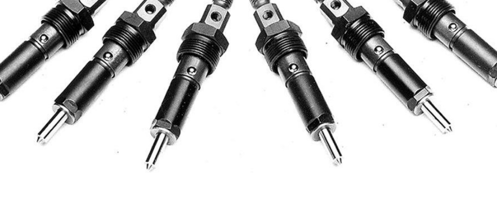
This kit contains replacement fuel injectors for 5.9L 12-Valve Cummins engines. BD’s flow-enhanced fuel injectors are made with new VCO-type 145-degree 5-hole nozzles and the highest degree of accuracy.
Available Sets
- 1040175 — +40HP 5.9L 6BTA 12V Injector Set
- 1040277 — +45HP 5.9L 12V Injector Set
- 1040278 — +90HP 5.9L 12V Injector Set
- 1040279 — +120HP 5.9L 12V Injector Set
Kit Contents
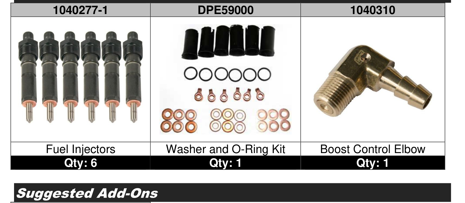
- Fuel Injectors (part #1040277-1) — Qty: 6
- Washer and O-Ring Kit (part #DPE59000) — Qty: 1
- Boost Control Elbow (part #1040310) — Qty: 1
Suggested Add-On
- BD ProForce 3D Torque Converter (part #1071217X)
Tools Required for Installation
- Wrenches
- Torque wrench
- Anti-seize compound
- Injector bore wire brush
- Hammer
- Brass drift
- Rust-penetrating solvent
- Injector puller
Torque Specifications
- Injector holddown nut — 60 N·m (44 ft-lbs)
- Drain manifold fitting screws (at injectors) — 8 N·m (6 ft-lbs)
- Drain manifold holddown clamp screws — 13 N·m (10 ft-lbs)
- High-pressure line at delivery valve holder — 30 N·m (22 ft-lbs)
- High-pressure line at fuel injector — 30 N·m (22 ft-lbs)
- Line clamp bracket bolts — 24 N·m (18 ft-lbs)
Removal
CAUTION: Disconnect both vehicle batteries before installation for safety.
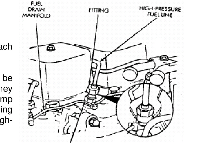
High-Pressure Fuel Line Removal
All high-pressure fuel lines are of the same length and inside diameter. Correct high-pressure fuel line usage and installation is critical to smooth engine operation.
IMPORTANT: The high-pressure fuel lines must be clamped securely in place in the holders. The lines cannot contact each other or other components. Do not attempt to weld high-pressure fuel lines or to repair lines that are damaged. Only use the recommended lines when replacement of a high-pressure fuel line is necessary.
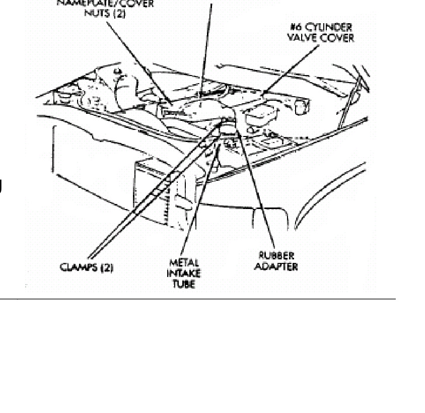
- Remove the nameplate/cover from the top of the six engine valve covers (two nuts).
- Remove the necessary clamps holding the lines to the engine.
- Clean the area around each line.
- Disconnect each line at the top of each fuel injector.
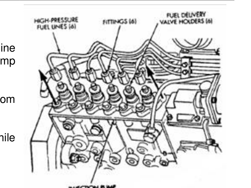
- Disconnect each high-pressure line fitting at each fuel injection pump delivery valve holder.
- Very carefully remove each line from the engine.
NOTE: High-pressure fuel lines must be installed in the same order that they were removed. Prevent injection pump delivery valve holders from turning when removing or installing high-pressure lines from the injection pump.
IMPORTANT: Do not bend the line while removing.
Fuel Drain Manifold Removal
- Remove the drain manifold fitting screws at each of the six injectors.
- Remove the fuel drain manifold holddown clamp mounting bolt at the top/rear of the intake manifold.
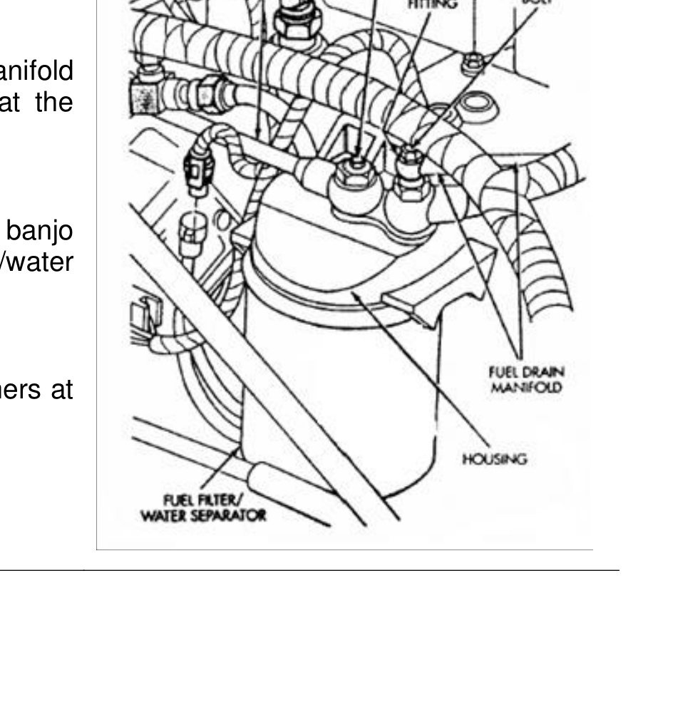
- Remove the fuel drain manifold banjo fitting at the top of the fuel filter/water separator (one bolt).
- Remove the fuel drain manifold washers at each fuel injector.
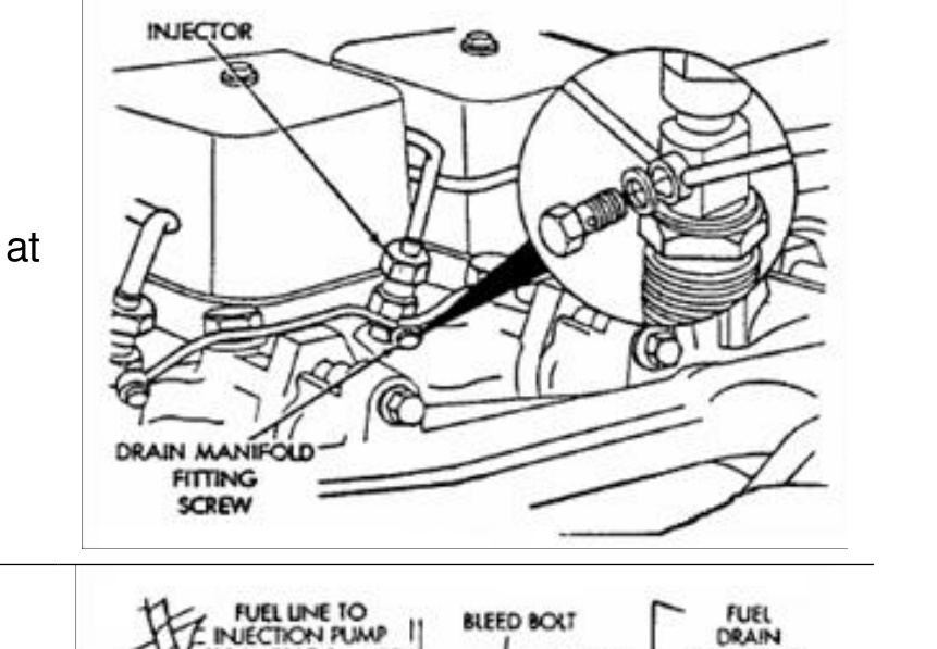
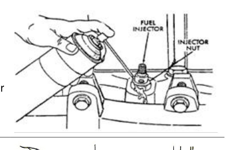
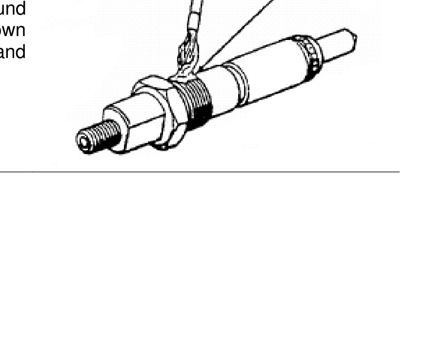
Fuel Injector Removal
- Thoroughly clean the area around the injector.
- Hit the injector body with a brass drift to loosen it.
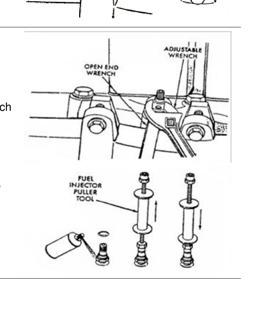
- Hold the injector body with one wrench while removing the injector nut with another.
NOTE: When rust has formed on the fuel injector nut, the injector can rotate in the cylinder head during removal. This may cause damage to the cylinder head bore. Use a rust-penetrating solvent before attempting to loosen a rusted holddown nut.
NOTE: It may be necessary to tap the injector with an injector puller tool.
Installation
Fuel Injector Installation
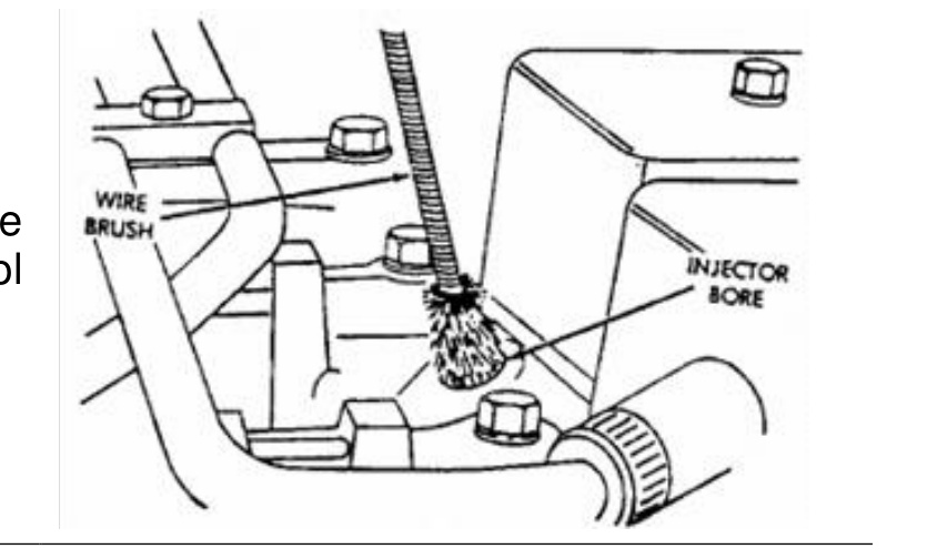
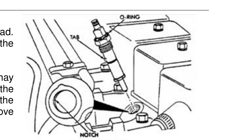
- Clean the injector cylinder head bore with a special Cummins wire brush tool or equivalent.
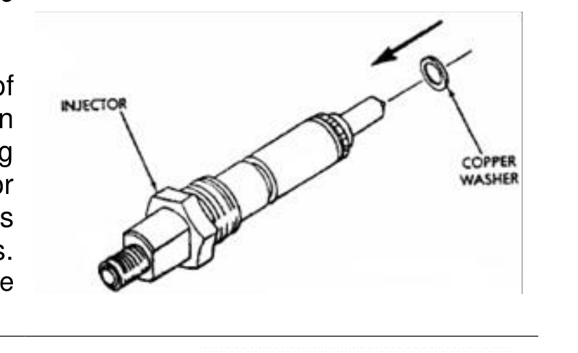
- Install a new copper washer on the injector.
- Apply a coating of anti-seize compound to the threads of the injector holddown nut and between the top of the nut and the injector body.
- Install the injector into the cylinder head. Align the tab on the injector to the notch in the cylinder bore.
- Tighten the injector holddown nut to 60 N·m (44 ft-lbs) torque.
NOTE: Two different thicknesses of injector tip washers have been included in this kit. When installing new injector washers, select washers that are the same thickness as the used washers from the old injectors. Keep in mind that the old washers have been crushed during installation.
NOTE: Certain types of injectors may have an O-ring located above the holddown nut. After tightening the injector, push the O-ring into the groove at the top of the injector.
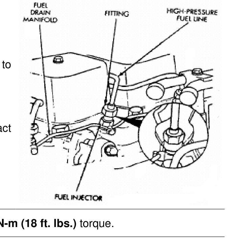
Fuel Drain Manifold Installation
- Using new seals and washers on all fittings, assemble the fuel drain manifold in reverse order of disassembly.
- Tighten the drain manifold fitting screws at the injectors to 8 N·m (6 ft-lbs) torque.
- Tighten the drain manifold holddown clamp screws to 13 N·m (10 ft-lbs) torque.
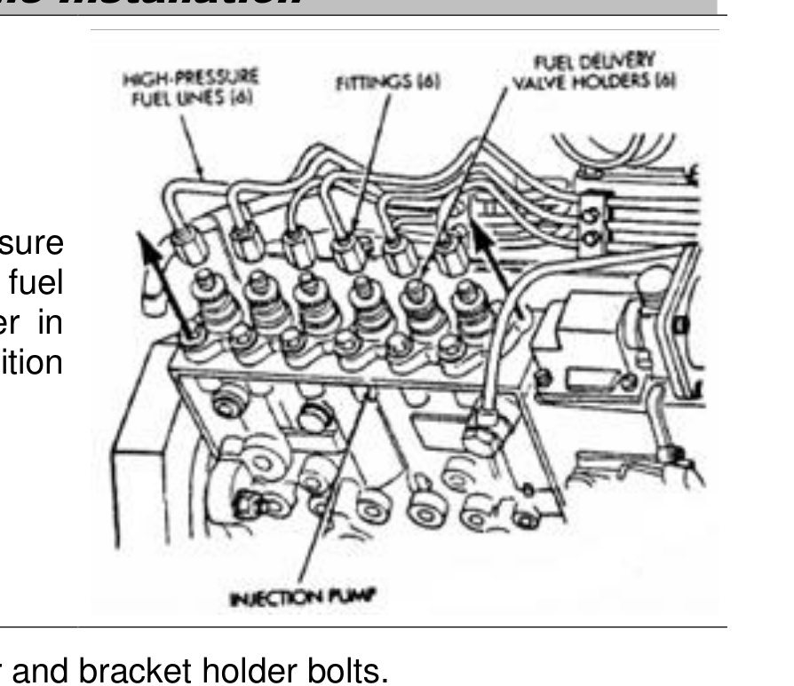
High-Pressure Fuel Line Installation
- Carefully position each high-pressure fuel line to the fuel injector and fuel injection pump delivery valve holder in the correct firing order. Also position each line in the correct line holder.
- Loosely install the line clamp isolator and bracket holder bolts.
- Tighten each line at the delivery valve holder to 30 N·m (22 ft-lbs) torque.
- Tighten each line at the fuel injector to 30 N·m (22 ft-lbs) torque.
- Tighten the clamp bracket bolts to 24 N·m (18 ft-lbs) torque.
- Reinstall the nameplate/cover.
- Bleed air from the fuel system and reconnect the batteries.
IMPORTANT: Fuel lines must not contact each other or any other component.
Boost Control Elbow Installation
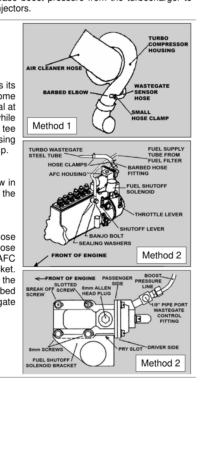
This elbow is recommended to increase boost pressure from the turbocharger to maximize the efficiency of the new fuel injectors.
Determine where your vehicle obtains its wastegate pressure signal. Some vehicles (method 1) pick up this signal at an elbow on the front of the turbo, while others (method 2) get the signal at a tee connected to the air fuel control (AFC) housing at the rear of the injection pump.
- Method 1: Replace the barbed elbow in the wastegate sensor hose with the boost control elbow.
- Method 2: Disconnect the barbed hose fitting from the wastegate sensor hose and remove the fitting from the AFC housing with a 7/16″ deep barrel socket. Install the boost control elbow into the 1/8″ NPT hole in place of the barbed hose fitting and reconnect the wastegate sensor hose.