
Installation instructions for the BD high-pressure common-rail fuel line kit for 2007.5-2018 Dodge 2500HD/3500HD/4500/5500 Cummins 6.7L ISB trucks. The kit includes all six injector feed lines for a complete, direct fit with no need to reuse the factory lines.
Download the Original PDF Manual
WARNING: Do not start the vehicle after installation until the fuel system has been primed. See the priming procedure at the end of this guide.
Introduction
This kit contains all 6 injector feed lines for Dodge Cummins 6.7L ISB applications, designed to provide a complete, direct fit with no need for the end user to bend any lines.
Applications
- 2007.5–2018 Dodge 2500HD / 3500HD / 4500 / 5500
- Cummins 6.7L ISB common-rail engine
- BD part #1050150 (Dodge 6.7L HP Fuel Line Kit)
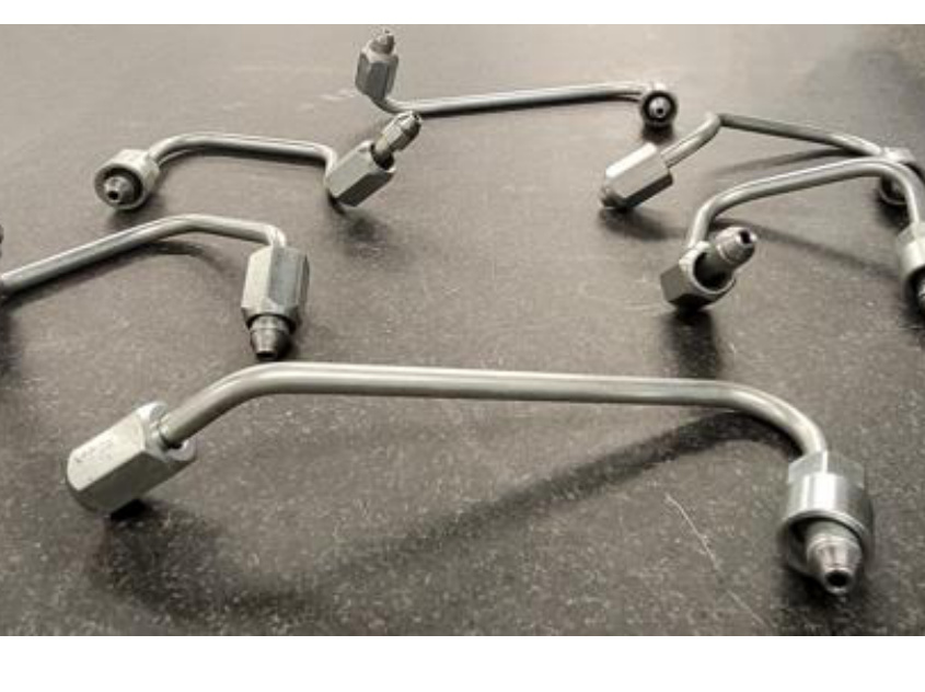
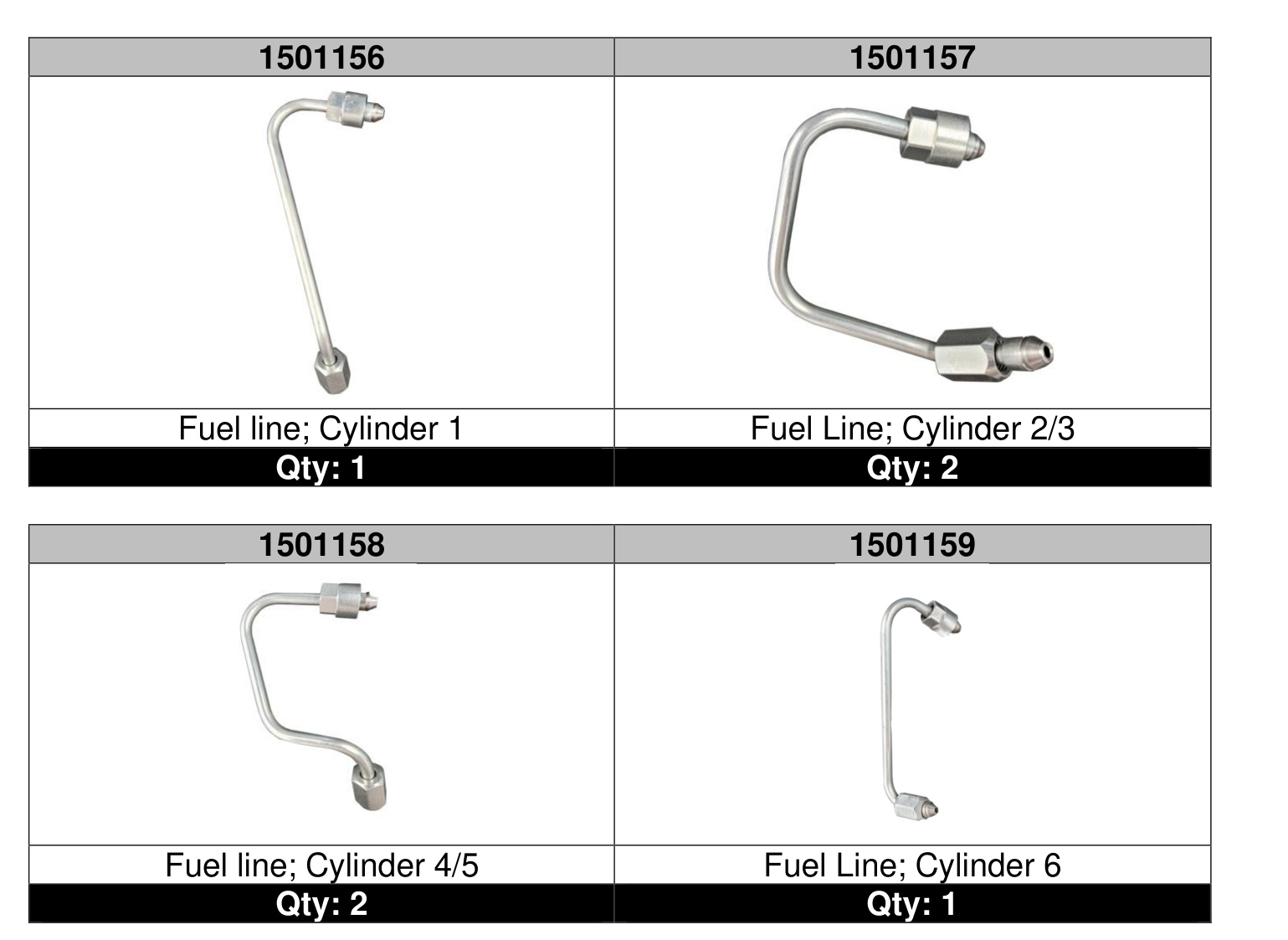
Kit Contents
- 1501156 — Fuel line, Cylinder 1 (Qty: 1)
- 1501157 — Fuel line, Cylinder 2/3 (Qty: 2)
- 1501158 — Fuel line, Cylinder 4/5 (Qty: 2)
- 1501159 — Fuel line, Cylinder 6 (Qty: 1)
Tools Required
- Cable tie
- 8, 10 and 11 mm sockets
- 24 mm wrench
- 19 mm crowfoot
- Torque wrench
- Ratchet and ratchet extensions
Torque Specifications
- Fuel tube nut at the cylinder head — 40 N·m (30 ft-lbs)
- Fuel tube nuts at the rail — 40 N·m (30 ft-lbs)
- Metal bracket at the rear of the cylinder head — 43 N·m (32 ft-lbs)
- Oil dipstick bolt — 24 N·m (18 ft-lbs)
- Oil dipstick nut — 9 N·m (80 in-lbs)
- Engine cover bolts — 10 N·m (89 in-lbs)
Disassembly
IMPORTANT: Disconnect both vehicle batteries before beginning installation for safety.
- Remove the engine oil dipstick (2). Remove the bolts (1) and lift off the engine cover (3).
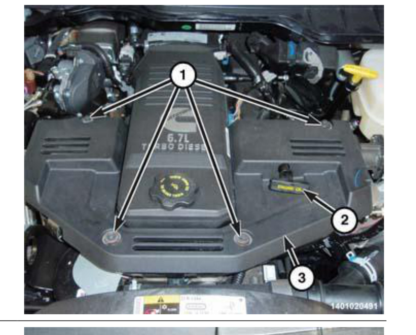
Engine cover bolts (1), oil dipstick (2) and engine cover (3). - Cut the cable tie and move aside the bulkhead connector (1).
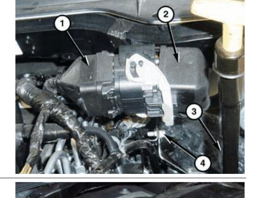
Bulkhead connector (1) — cut the cable tie and move it aside. - Disconnect the exhaust pressure sensor wire harness connector (2), then the EGR cooler bypass valve wire harness connector (1).
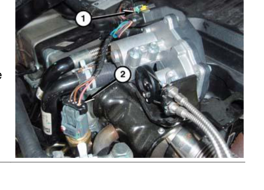
EGR cooler bypass valve connector (1) and exhaust pressure sensor connector (2). - Disconnect the crankcase pressure sensor 2 wire harness connector (1).
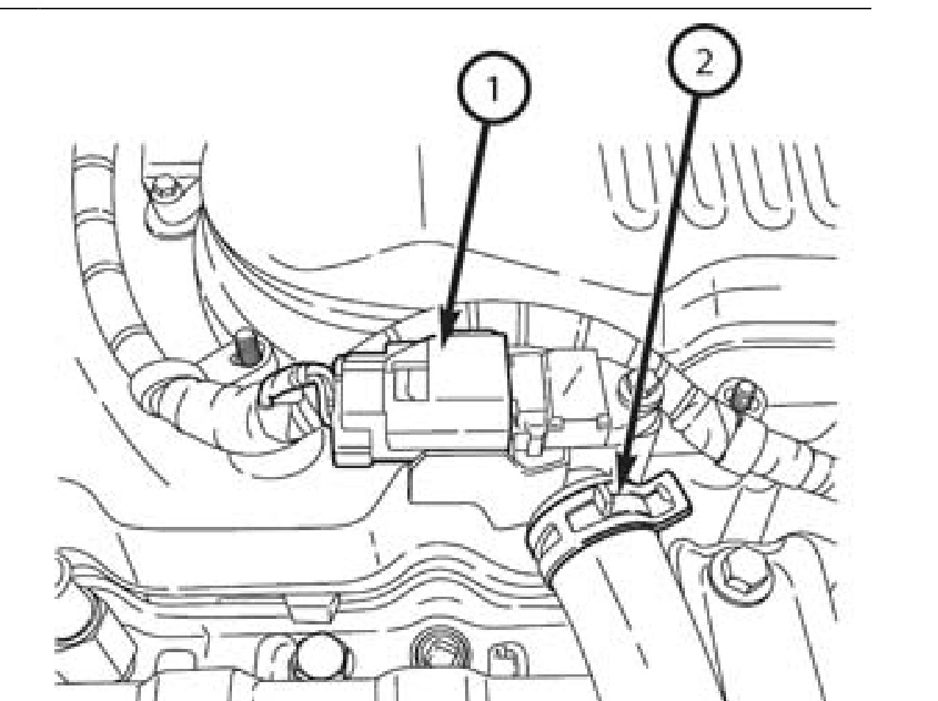
Crankcase pressure sensor 2 connector (1). - Disconnect the crankcase pressure sensor 1 wire harness connectors (7).
Crankcase pressure sensor 1 wire harness connectors. - Disconnect both fuel injector harness connectors (1).
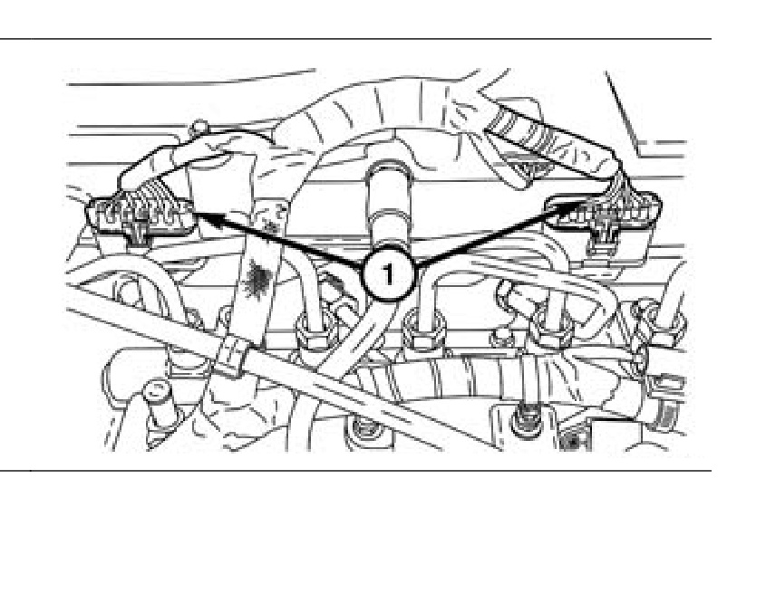
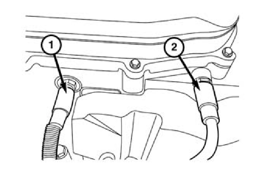
Both fuel injector harness connectors (1). - Remove the CCV (crankcase ventilation) oil drain hoses (1, 2) from the cylinder head cover.
CCV oil drain hoses (1, 2). - Remove the fuel tube silencer (1).
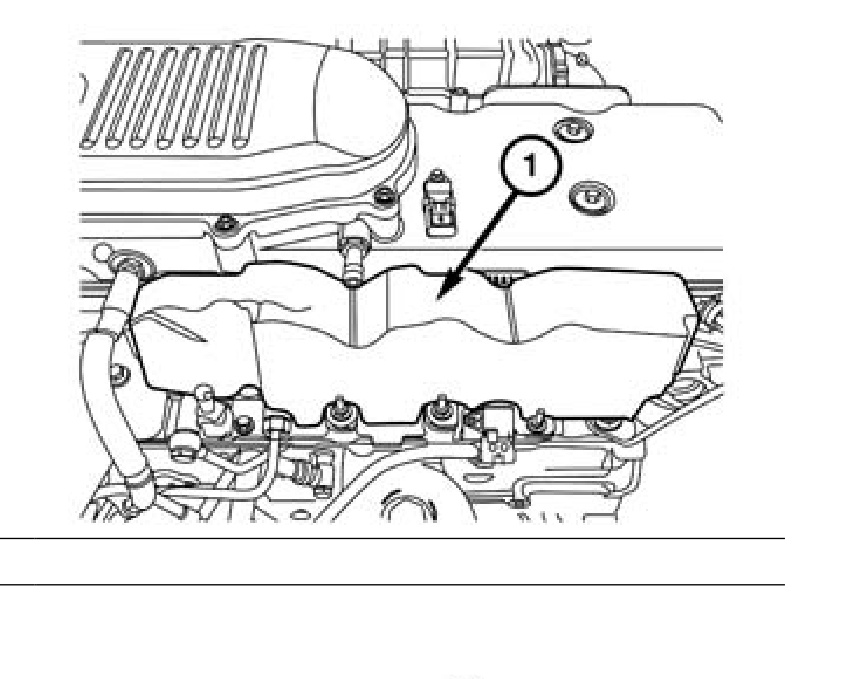
Fuel tube silencer (1). - Remove the intake manifold.
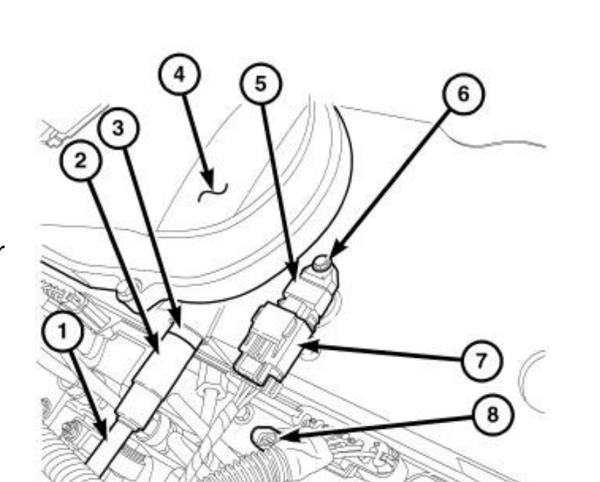
- Remove the bracket (5) located above the fuel tube connection at the cylinder head. Two bolts (4) secure this bracket to the rear of the cylinder head; the upper bolt hole is slotted. Loosen — but do not remove — these two bracket bolts, then tilt the bracket down.
- Remove the fuel injector lines. Refer to the diagram below for the rail, fittings, and bracket layout.
WARNING: When loosening or tightening the high-pressure lines attached to a separate fitting (13), use a backup wrench on the fitting. Do not allow the fittings to rotate — damage to both the fuel line and the fitting will result.
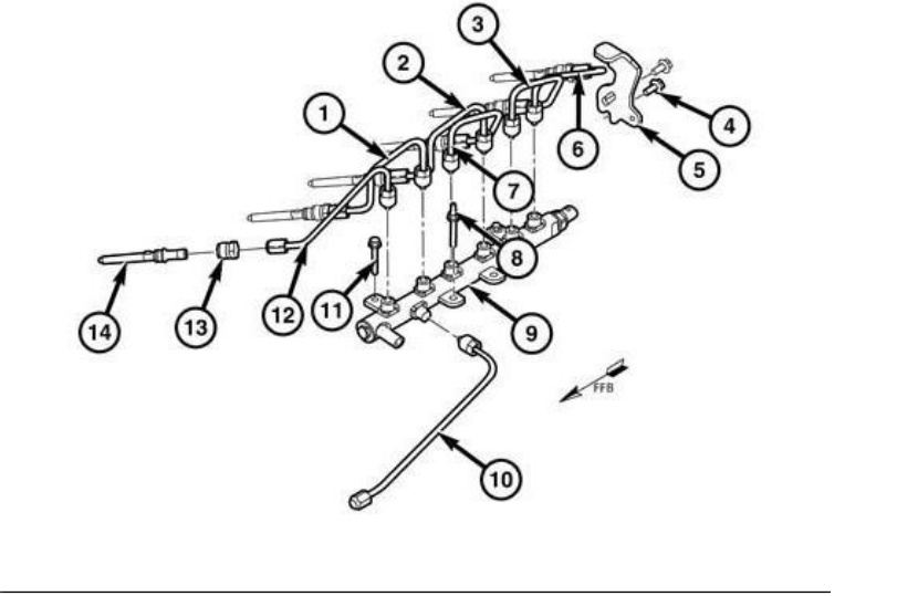
Fuel rail, high-pressure lines, separate line fittings (13) and rear cylinder-head bracket (5).
Installing the New Fuel Lines
IMPORTANT: If you are also installing injectors, install them now — before reassembling the fuel lines.
Installation is the reverse of the disassembly procedure. Reinstall the new injector feed lines, intake manifold, fuel tube silencer, CCV hoses, bracket and all harness connectors, then tighten to the following torque specifications:
- Fuel tube nut at the cylinder head — 40 N·m (30 ft-lbs)
- Fuel tube nuts at the rail — 40 N·m (30 ft-lbs)
- Metal bracket at the rear of the cylinder head — 43 N·m (32 ft-lbs)
- Oil dipstick bolt — 24 N·m (18 ft-lbs); nut — 9 N·m (80 in-lbs)
- Engine cover bolts — 10 N·m (89 in-lbs)
WARNING: Prime the fuel system before starting the vehicle (see below).
Fuel System Priming
- Turn the key to the CRANK position and quickly release it to the ON position before the engine starts. This operates the fuel transfer (lift) pump for 25 seconds.
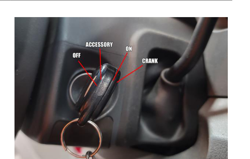
Ignition key positions — OFF, ACCESSORY, ON and CRANK. - Crank the engine. If it does not start after 25 seconds, turn the key to OFF and leave it for at least 10 seconds, then repeat the previous step until the engine starts. Fuel system priming is now complete.
- Attempt to start the engine. When the engine does start, it may run erratically and be noisy for a few minutes — this is normal. If the engine fails to start, proceed to the steps below.
CAUTION: Do not engage the starter motor for more than 30 seconds at a time. Allow 2 minutes between cranking intervals.
If the Engine Still Will Not Start
- Repeat the fuel priming procedure using the fuel transfer (lift) pump. Be sure fuel is present at the fuel tank.
- Crank the engine for 30 seconds at a time to allow the fuel system to prime.
WARNING: The fuel injection pump supplies extremely high fuel pressure to each individual injector through the HP lines. Fuel under this pressure can penetrate skin and cause personal injury. Wear safety goggles and adequate protective clothing. Do not loosen fuel fittings while the engine is running.
WARNING: The engine may start while you are cranking the starter motor.
Final Inspection
IMPORTANT: Once all components have been reinstalled, confirm that all connection points are tight and inspect the entire fuel system for leaks.