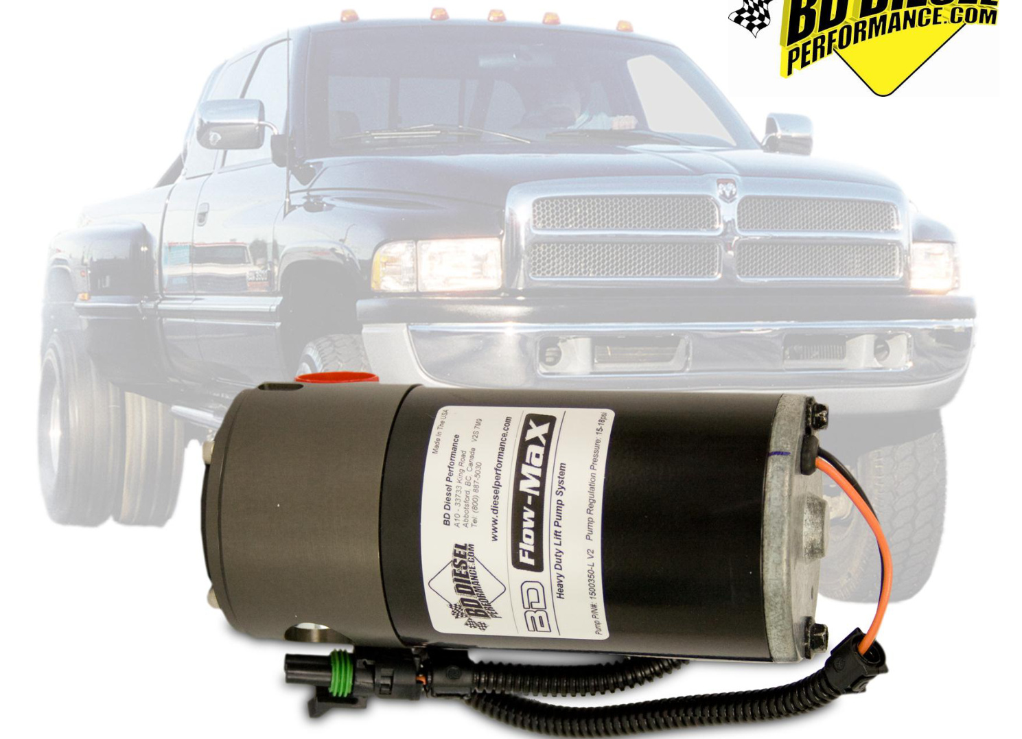
Installation instructions for the BD FlowMAX lift pump kit, part #1050301B, designed for 1998-2002 Dodge Cummins 24V ISB engines. This kit delivers steady, enhanced fuel flow to protect your injection pump. The guide covers kit contents, required tools, and complete step-by-step installation.
Download the Original PDF Manual
IMPORTANT: Please read all instructions carefully before beginning the installation.
Kit Contents
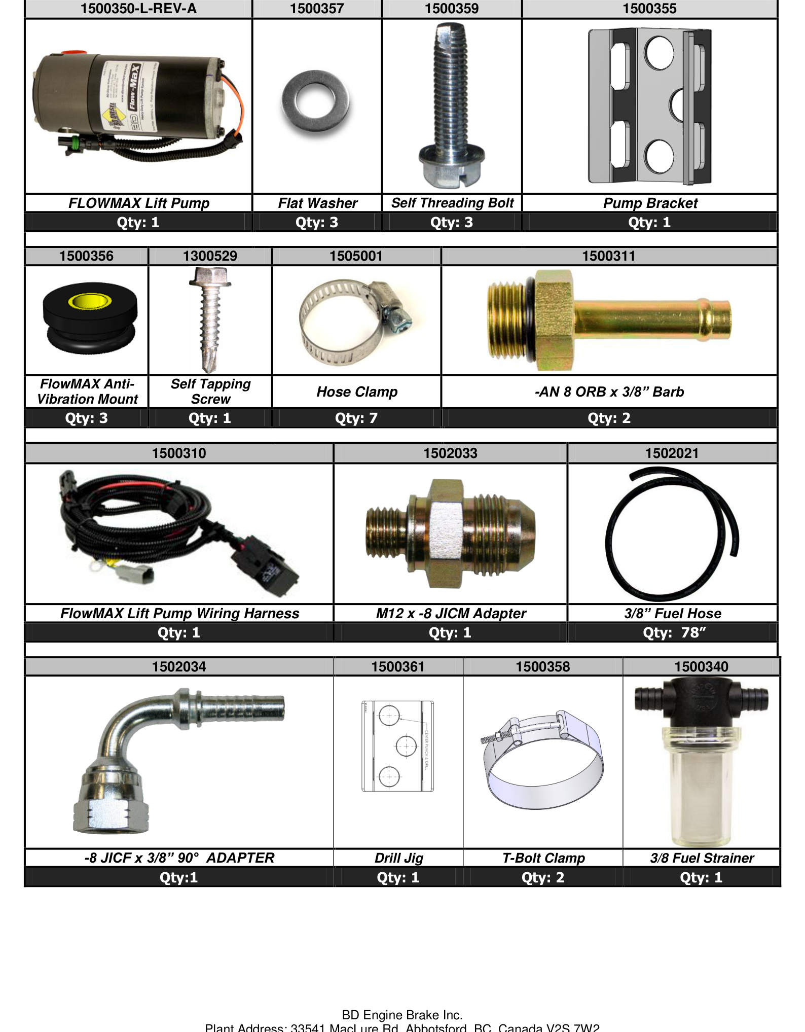
Verify that all parts are present before you begin (part list 1500350-L-REV-A):
- FlowMAX Lift Pump — Qty 1 (1500350-L-REV-A)
- Flat Washer — Qty 3 (1500357)
- Self-Threading Bolt — Qty 3 (1500359)
- Pump Bracket — Qty 1 (1500355)
- FlowMAX Anti-Vibration Mount — Qty 3 (1500356)
- Self-Tapping Screw — Qty 1 (1300529)
- Hose Clamp — Qty 7 (1505001)
- -AN 8 ORB x 3/8″ Barb fitting — Qty 2 (1500311)
- FlowMAX Lift Pump Wiring Harness — Qty 1 (1500310)
- M12 x -8 JICM Adapter — Qty 1 (1502033)
- 3/8″ Fuel Hose — Qty 78″ (1502021)
- -8 JICF x 3/8″ 90° Adapter — Qty 1 (1502034)
- Drill Jig — Qty 1 (1500361)
- T-Bolt Clamp — Qty 2 (1500358)
- 3/8 Fuel Strainer — Qty 1 (1500340)
Before You Begin
The FlowMAX pump is designed to be a stand-alone pump system and is not intended to be used in conjunction with a stock lift pump. If your truck has been retrofitted with the Chrysler in-tank lift pump, you will have to lower the fuel tank and delete the pump from inside the tank. BD offers a simple retrofit kit complete with instructions and the pieces needed to do this, part number 1050302.
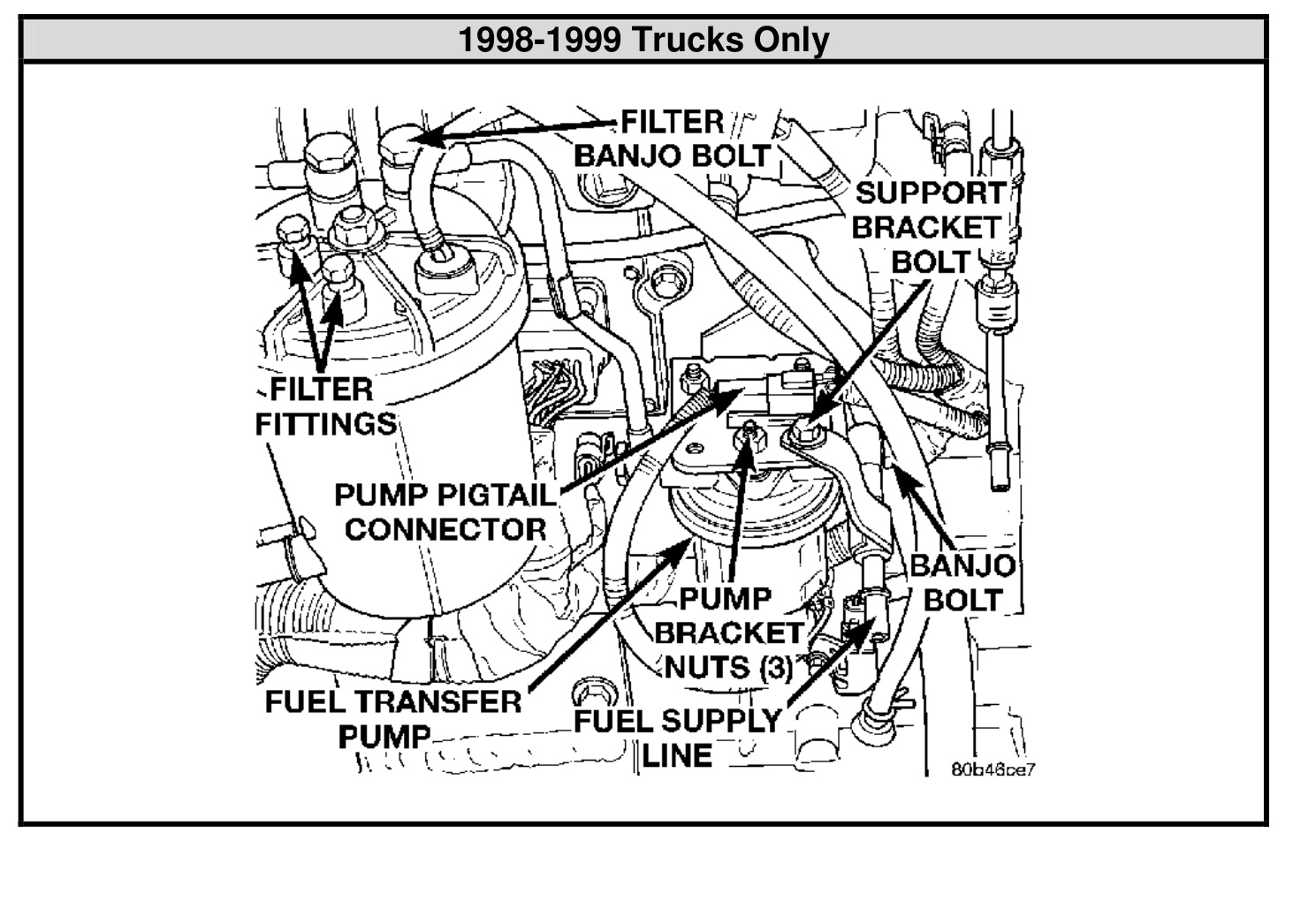
If you are unsure whether your truck has been retrofitted, simply check that the factory lift pump is still in place on the engine next to the fuel filter housing (see the engine diagrams in Step 7 below). If it is not there, then your truck has the in-tank pump.
Optional Accessories
- 1081130 — Low Fuel Pressure LED Alarm kit
- 1085210 — X-Monitor Digital Gauge Package
- 1080156 — Fuel Pressure Kit (X-Monitor Accessory)
Tools Required
- 5 mm Allen wrench
- Drill
- 1/8″ and 11/32″ drill bits
- Pliers
- 3/16″ flat screwdriver
- 10 mm socket or wrench
- Small pipe cutter
- Knife to cut fuel hose
- 9/16″ socket or wrench
- 7/16″ socket or wrench
Installation
Preparation
- Disconnect both batteries.
- Raise the vehicle and support it safely.
- Unbolt the front driveshaft (4x4 only) for ease of installation.
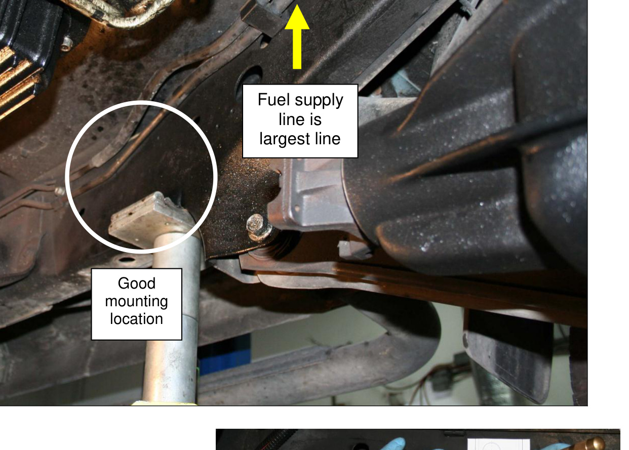
Pump Mounting
Locate a spot on the inside of the driver’s side frame rail near the front of the vehicle so that there is room to use a drill. Tape the drill template in place. Ensure there is ample room and that nothing will contact the pump in this location.
- Center punch the three holes, remove the drill template, and drill a pilot hole to 1/8″. Then re-drill to 11/32″.
- Insert the three rubber isolators into the support bracket. Use some water to help lubricate the isolators as they slide into the bracket. Place the large washers on the inside of the bracket against the rubber isolators. Using an air ratchet (9/16″ socket), tighten the self-threading 3/8″ bolt through each hole of the support bracket assembly and into the frame. Repeat for the other two bolts. Torque the three bolts to 25 ft-lbs.
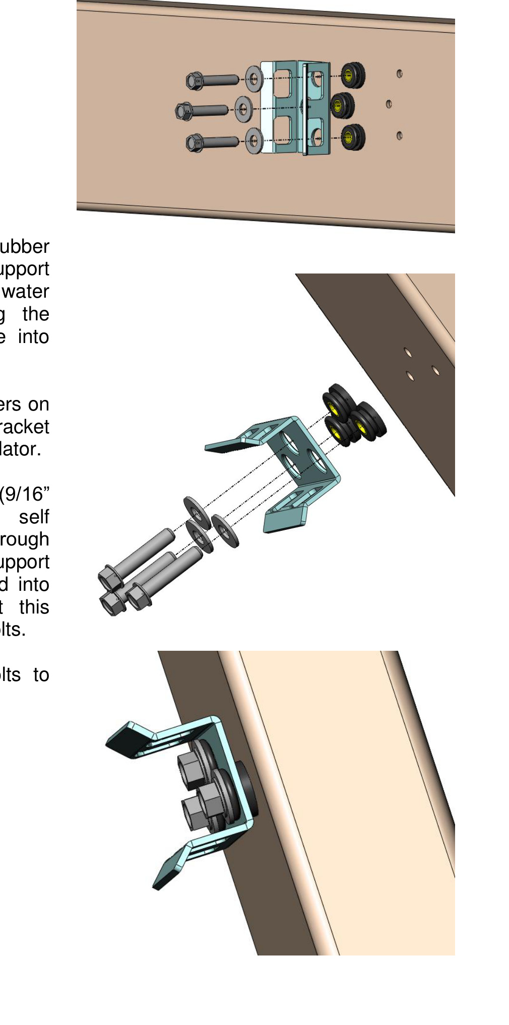
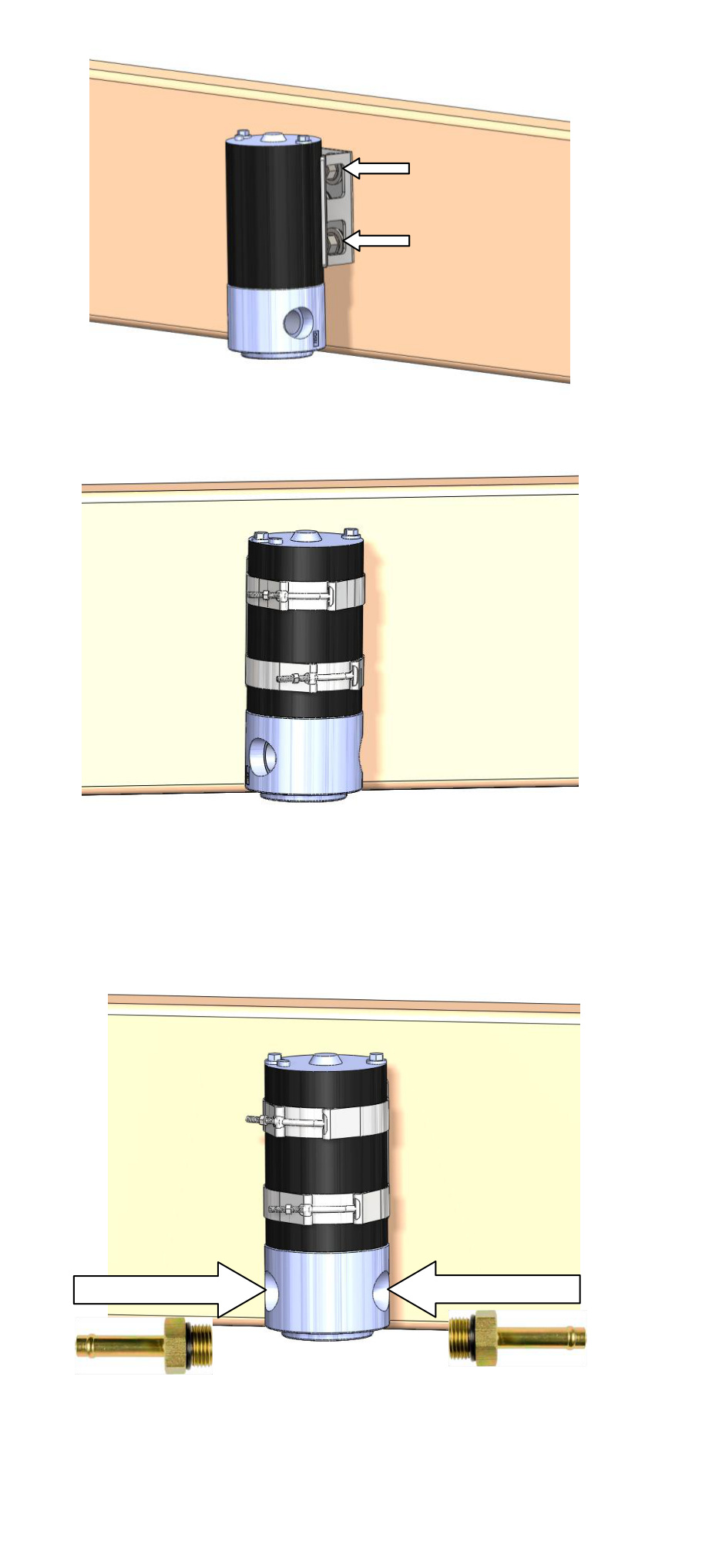
- Locate the two supplied T-bolt band clamps and unthread the nut (7/16″ socket) from each. Spread the clamps apart and insert them through the boxed cutouts. With both clamps inserted, place the pump into position and align the inlet and outlet parallel to the frame. The inlet should point toward the fuel tank. Tighten the clamps around the motor body, not the aluminum pump head. Torque the nuts to 80 in-lbs.
- Insert the ORB-Barb fittings into the inlet and outlet of the pump. Do not over-tighten, as they use an O-ring for sealing.
Fuel Line Routing
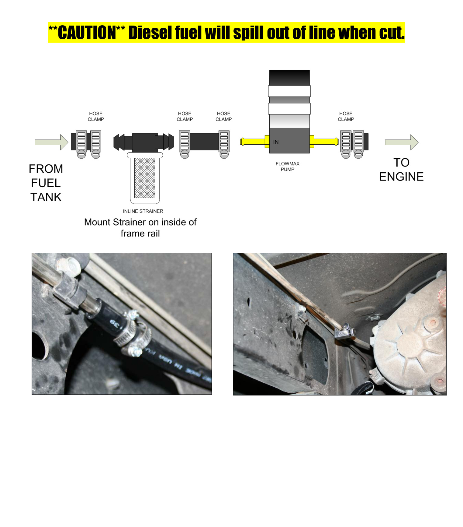
- Install the rubber hose onto the inlet (IN) side of the pump using one hose clamp, and run the line about 5″ toward the rear of the vehicle. Cut the hose at the 5″–6″ length. Install the supplied inline strainer with a hose clamp on each end. Continue to route the supplied fuel line toward the rear of the vehicle over the skid plate. Locate a suitable spot and cut the fuel supply line with respect to the stock fuel-line clamp and skid plate. Be sure to use a tube cutter.
CAUTION: Diesel fuel will spill out of the line when it is cut. Have an approved container and rags ready to capture the fuel.
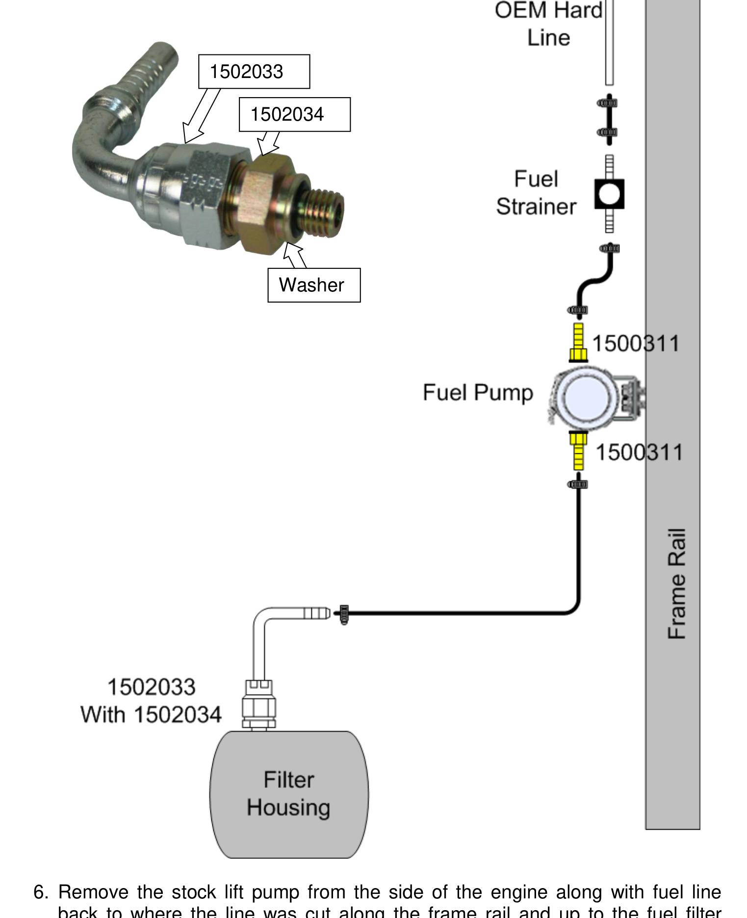
- Remove the stock lift pump from the side of the engine, along with the fuel line, back to where the line was cut along the frame rail and up to the fuel filter bowl. At the fuel bowl, the banjo bolt will need to be removed as well, since it is being replaced.
Filter Housing Connection
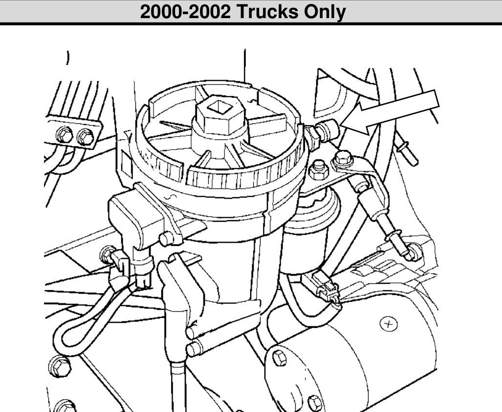
Use the diagrams below to identify the fuel filter housing fittings for your model year.
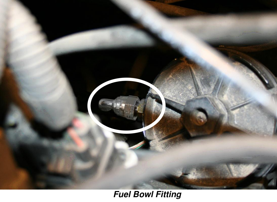
- Thread the JICM adapter (1502033) into the fuel filter bowl and tighten first. Do not over-torque, as this is an O-ring seal. Then thread on the JICF adapter (1502034), position the barbed end, and tighten.
NOTE: The JICM adapter has a loose washer around the O-ring — ensure it does not fall off the adapter during installation.Run the remaining fuel line from the fuel filter bowl down to the fuel pump, with one clamp on the filter-bowl adapter assembly and one on the fuel pump fitting, making sure to run the line to the outlet (OUT) side of the pump. Remove the excess fuel line before installing on the outlet and clamping.
- 1998-99: adapter installs at the top of the filter housing.
- 2000-02: adapter installs at the rear of the filter housing.
Wiring
- Lay out the wiring harness so that it can be plugged into the stock fuel pump harness and into the new FlowMAX fuel pump, and place the positive and negative terminals in their approximate routing. Once the routing paths have been chosen and laid out, install the relay to the firewall using the self-tapping screw.
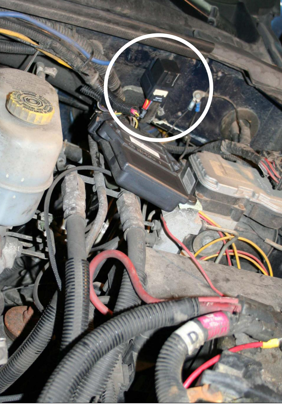
- Attach the wiring using the supplied tie wraps so it is kept away from hot surfaces and/or moving components. Once the wiring is attached and everything is in place, the positive and negative terminals can be attached to the battery.
Final Assembly
- Make sure that all fuel lines and wiring harnesses are fixed securely in place.
- Re-install the front driveshaft (4x4 models only).
- Lower the vehicle and re-install the battery cables.
NOTE: The pump will develop 15–18 psi at idle with 14 VDC. If your battery voltage is lower, the pressure will be lower as well.
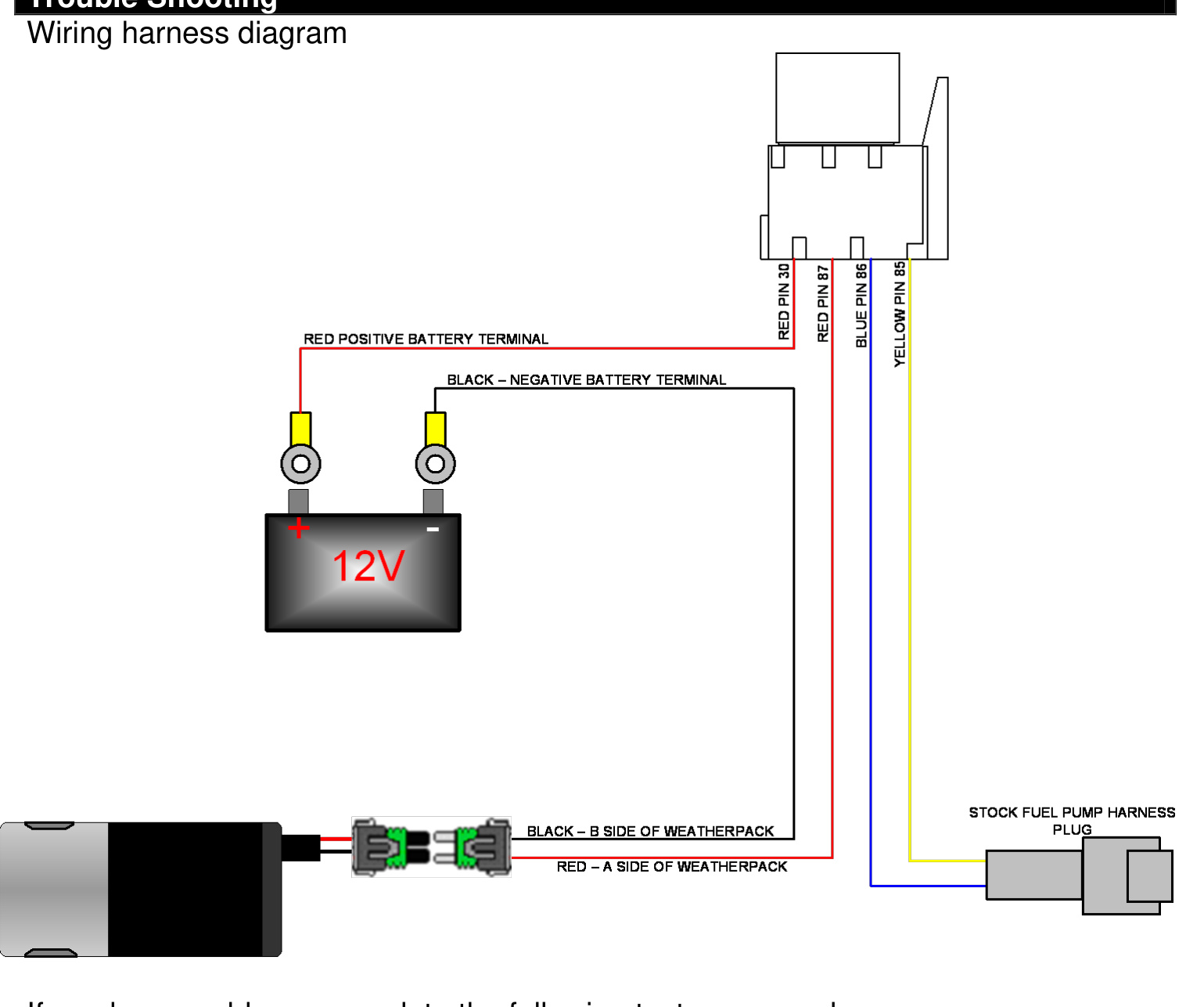
Troubleshooting
If you experience any problems, complete the following tests or procedures:
- Clean and re-tighten the battery terminals.
- Ensure there are no crimped or pinched sections of fuel line.
- Change the fuel filter.
- Check that you have at least 12 volts at the electrical connector at the pump.
- Check that the fuse in the supplied harness near the battery terminal is not blown.
- Check that all plugs are securely clipped together.
- Run a hose from a fuel can full of diesel to the pump inlet to see if the pressure changes. If the pressure increases, the problem is a restriction in the line — possibly a clogged fuel screen.