
Installation instructions for the BD FlowMAX auxiliary lift pump kit, part #1050305B, for 2003-2004.5 Dodge Cummins trucks. The kit provides the safety and performance of enhanced fuel flow to your Cummins engine. This guide covers kit contents and full installation.
Download the Original PDF Manual
IMPORTANT: Please read all instructions carefully before beginning the installation.
Kit Contents
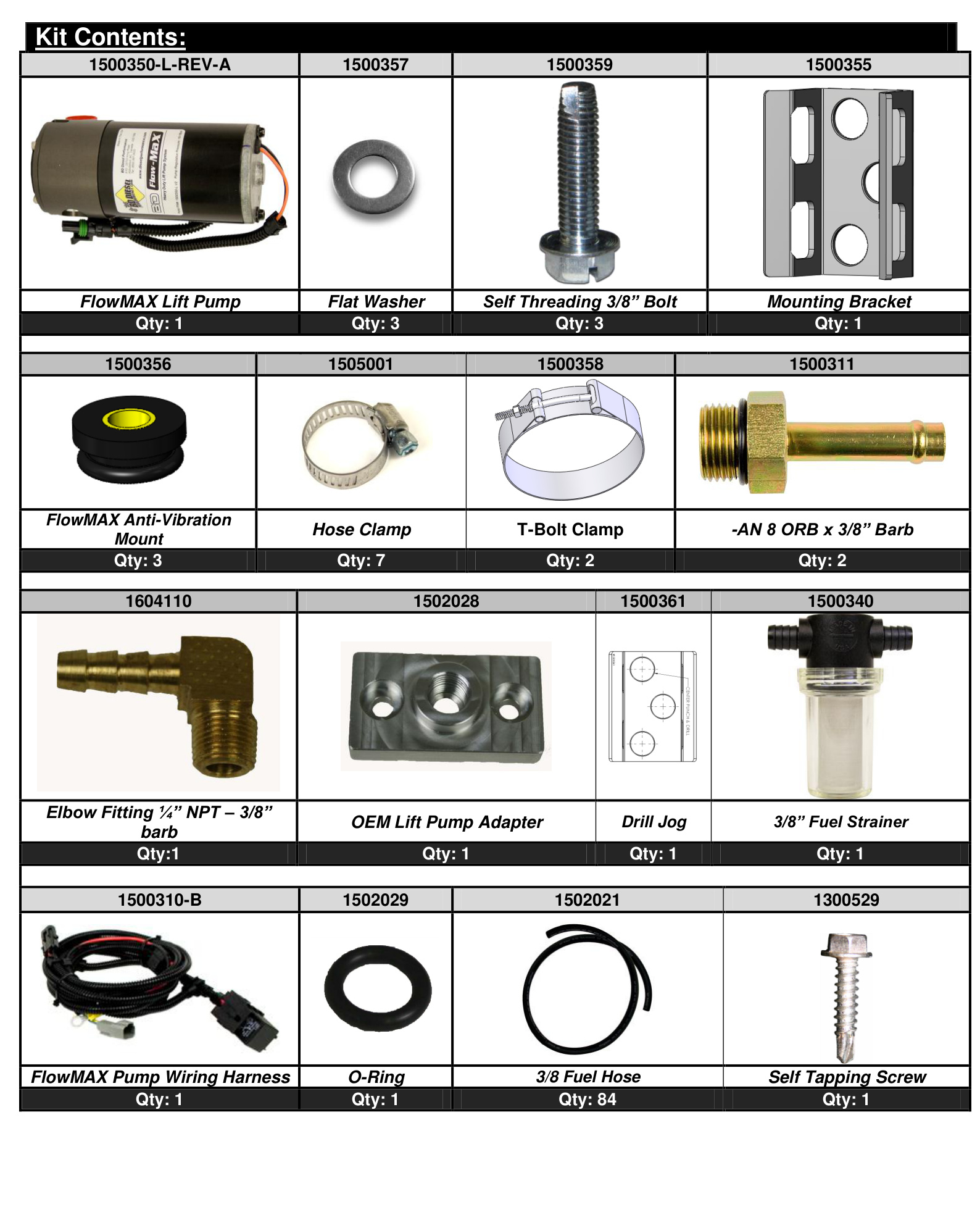
Kit reference 1500350-L-REV-A. Confirm all parts are present before you begin:
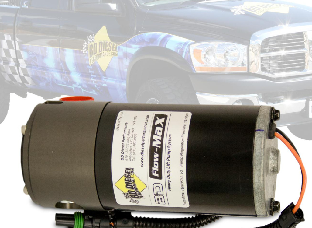
- FlowMAX Lift Pump — Qty 1 (#1500350-L-REV-A)
- Flat Washer — Qty 3 (#1500357)
- Self-Threading 3/8″ Bolt — Qty 3 (#1500359)
- Mounting Bracket — Qty 1 (#1500355)
- FlowMAX Anti-Vibration Mount — Qty 3 (#1500356)
- Hose Clamp — Qty 7 (#1505001)
- T-Bolt Clamp — Qty 2 (#1500358)
- -AN 8 ORB x 3/8″ Barb — Qty 2 (#1500311)
- Elbow Fitting 1/4″ NPT – 3/8″ Barb — Qty 1 (#1604110)
- OEM Lift Pump Adapter — Qty 1 (#1502028)
- Drill Jig — Qty 1 (#1500361)
- 3/8″ Fuel Strainer — Qty 1 (#1500340)
- FlowMAX Pump Wiring Harness — Qty 1 (#1500310-B)
- O-Ring — Qty 1 (#1502029)
- 3/8 Fuel Hose — Qty 84″ (#1502021)
- Self-Tapping Screw — Qty 1 (#1300529)
Before You Begin
The FlowMAX pump is designed to be a stand-alone pump system and is not intended to be used in conjunction with a stock lift pump. If your truck has been retrofitted with the Chrysler in-tank lift pump, you will have to lower the fuel tank and delete the pump from the tank. BD offers a simple retrofit kit complete with instructions and the pieces needed to do this, part number 1050302.
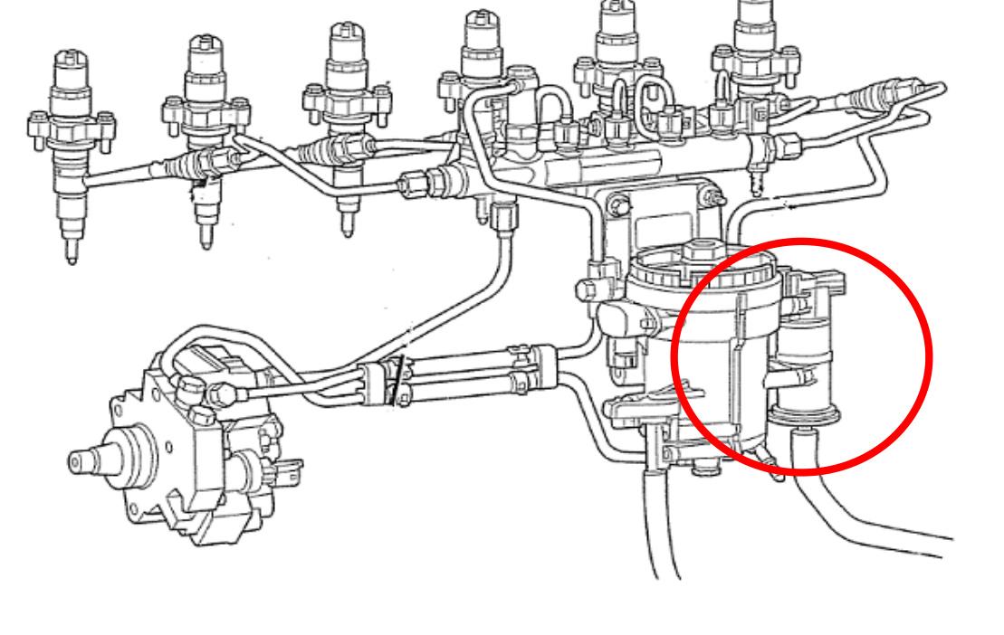
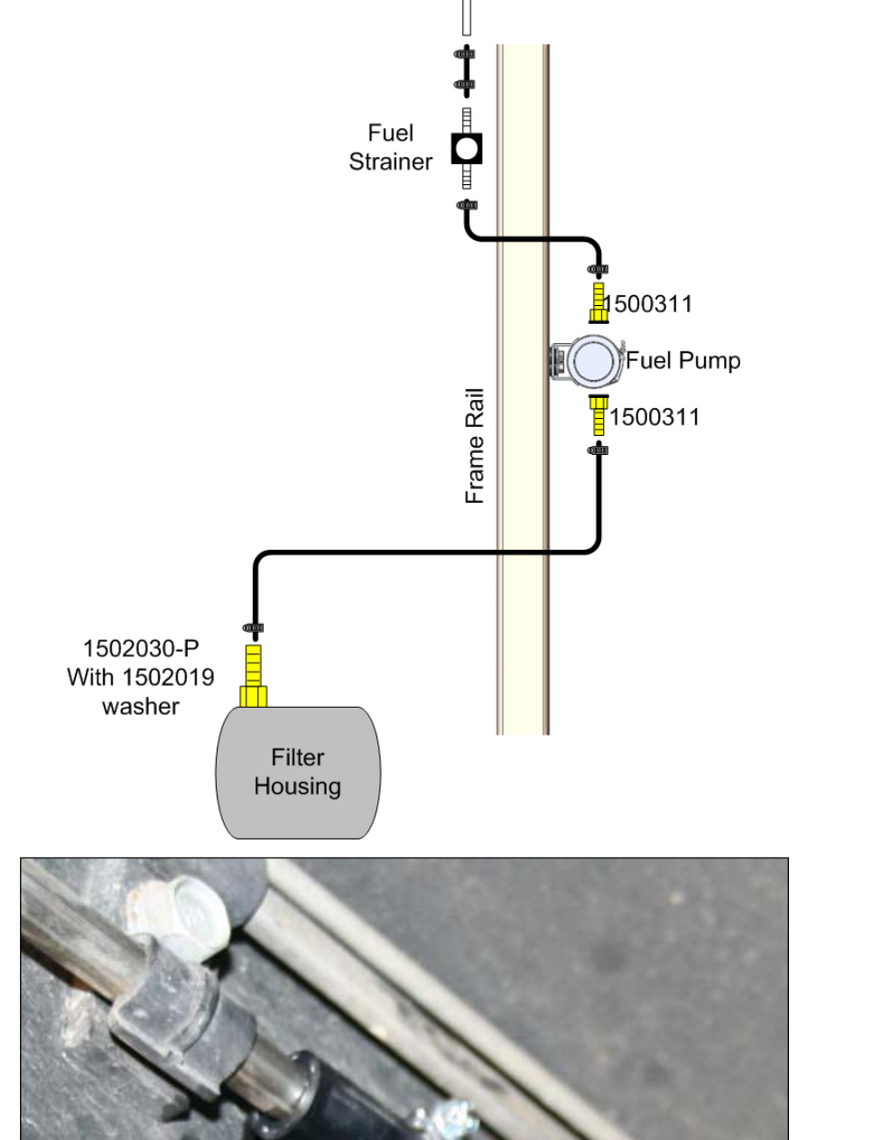
If you are unsure whether your truck has been retrofitted, simply check that the factory lift pump is still in place on the engine next to the fuel filter housing (see the diagram below). If it is not there, then your truck has the in-tank pump.
Optional Accessories
- 1081130 — Low Fuel Pressure LED Alarm kit
- 1085220 — X-Monitor Digital Gauge Package (2003-07)
- 1080156 — Fuel Pressure Kit (X-Monitor Accessory)
Tools Required
- 5 mm Allen wrench
- Drill
- 1/8″ and 21/64″ drill bits
- Pliers
- 3/16″ flat screwdriver
- 10 mm socket or wrench
- Small pipe cutter
- Knife to cut fuel hose
- 7/16″ socket or wrench
- 9/16″ socket or wrench
Installation
Remove the Factory Lift Pump & Fit the Bypass Adapter
- Disconnect both batteries.
- Raise the vehicle and support it safely.
- Locate and remove the factory lift pump. The pump is supported by four 5 mm socket-cap screws.
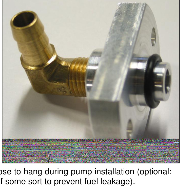
- Install the brass 90° NPT-to-barb fitting into the supplied aluminum pump bypass bracket. The brass elbow should be oriented so that the barbed end points down, or oriented 90° to the mounting holes. Use Teflon sealant to seal the threads.
- Install the new O-ring on the fuel-filter end of the adapter. Be sure to lubricate the O-ring before installing.
- Position and press the bypass adapter onto the fuel filter housing. Do not use the mounting bolts to draw the bypass adapter into the filter housing.
- Be sure the bypass adapter is positioned flat against the fuel filter housing. Install the mounting bolts and evenly tighten to 7 N·m (61 in-lbs).
- Connect the fuel-line extension hose to the brass barb fuel fitting. Make sure that, by re-routing the hose, it does not rub on anything. Allow the hose to hang during pump installation (optional: pinch the hose with vise grips or clamps to prevent fuel leakage).
Drill the Mounting Holes
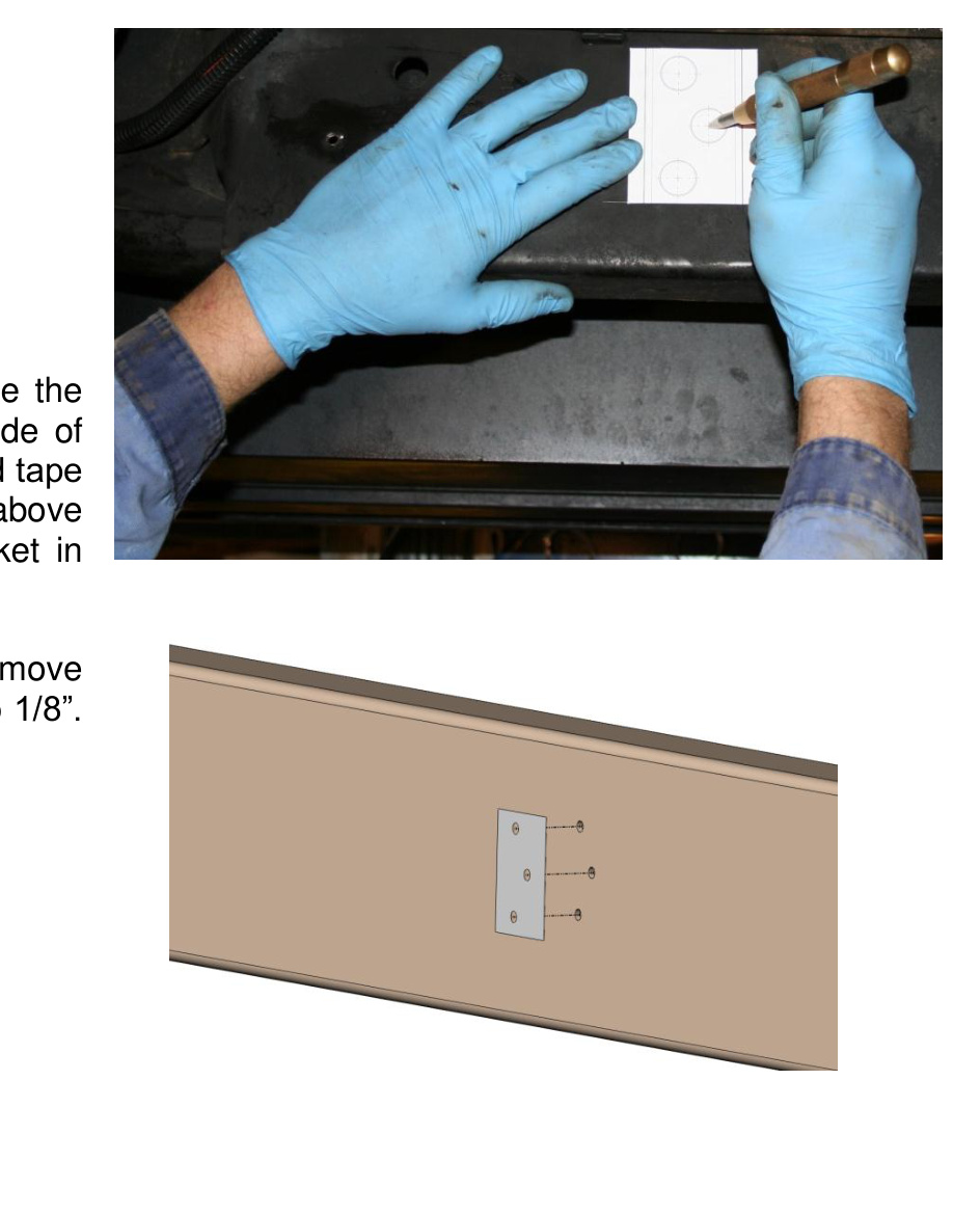
- From underneath the vehicle, locate the cross-member bracket on the inside of the driver’s frame rail. Position and tape the drill template onto the frame rail just above the weld. Place the fuel pump and bracket in place to ensure ample clearance. Mark the holes with a center punch. Remove the drill template, drill the pilot holes to 1/8″, then drill the main holes to 21/64″.
Mount the Support Bracket
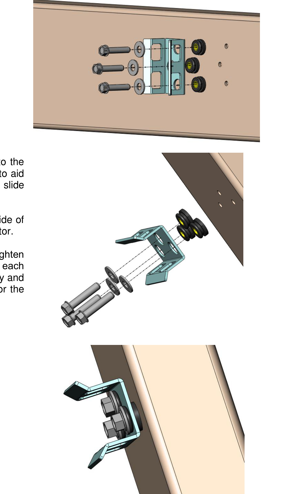
- Insert the three rubber isolators into the support bracket. Use a little water to help lubricate the isolators as they slide into the bracket. Place the large washers on the inside of the bracket against each rubber isolator. Using an air ratchet (9/16″ socket), tighten a self-threading 3/8″ bolt through each hole of the support-bracket assembly and into the frame. Repeat for the other two bolts. Torque the three bolts to 25 ft-lbs.
Mount the Pump & Fit the Inlet/Outlet Fittings
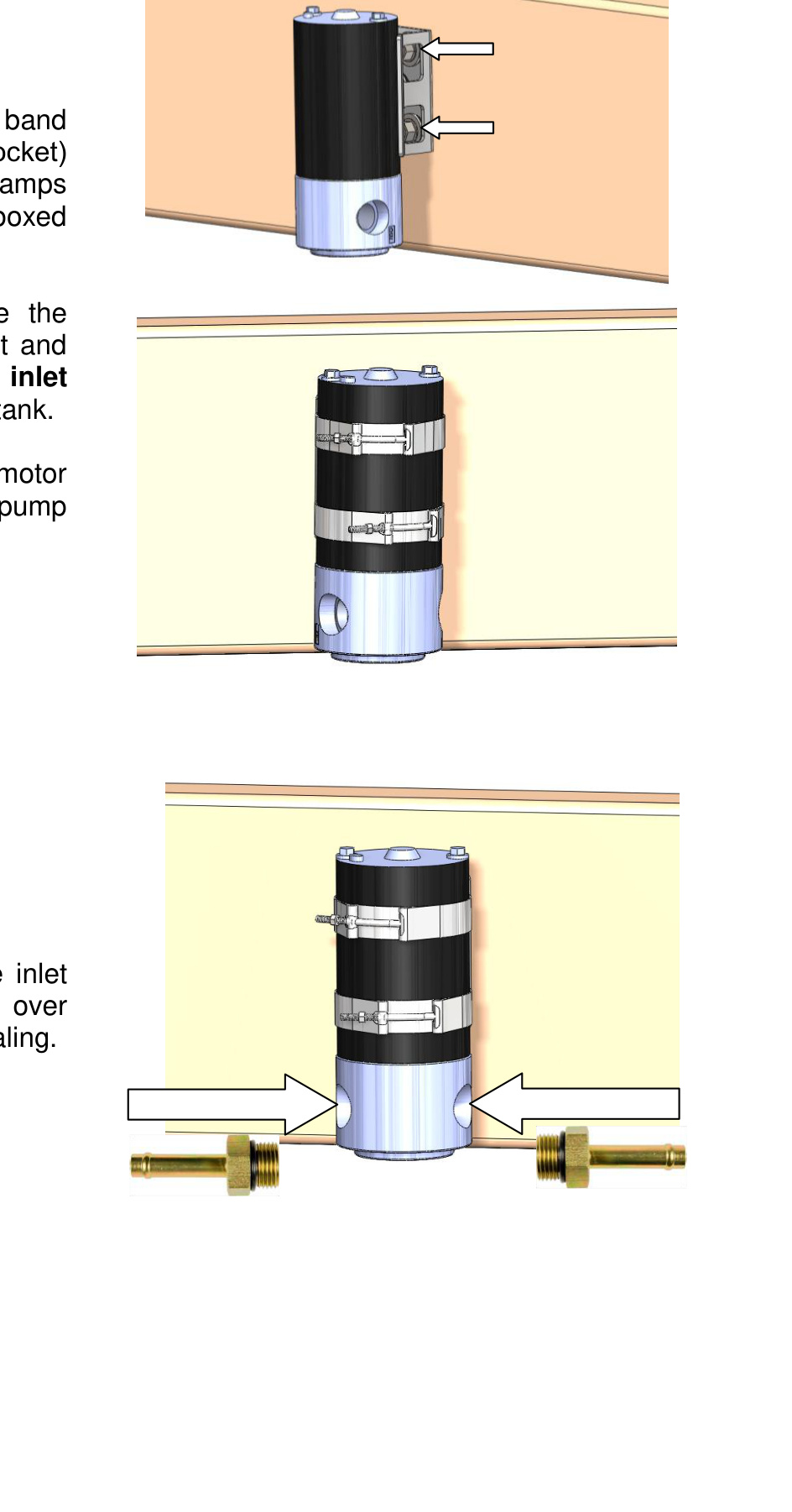
- Locate the two supplied T-bolt band clamps and unthread the nut (7/16″ socket) from each. Spread the clamps apart and insert them through the boxed cutouts. With both clamps inserted, place the pump into position and align the inlet and outlet parallel to the frame — the inlet should point toward the fuel tank. Tighten the clamps around the motor body, rather than the aluminum pump head, and torque the nuts to 80 in-lbs.
- Insert the ORB-barb fittings into the inlet and outlet of the pump. Do not over-tighten, as they use an O-ring for sealing.
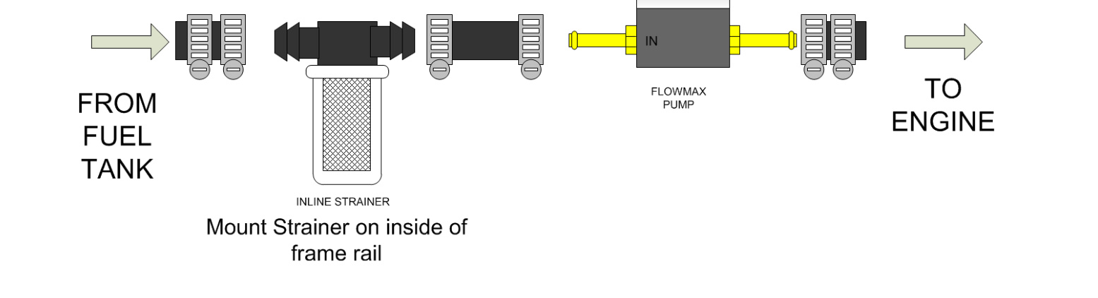
Plumb the Fuel Lines
- With the pump mounted, cut the hard fuel line about 12″ ahead of the pump on the inside of the frame rail. The fuel supply line is the thickest of the three lines. Discard the cut-off portion. A tube cutter does not need to be used for this cut.
- Route the fuel line that you connected from the front of the vehicle to the outlet of the pump. Use a hose clamp to secure this connection. Trim to fit; the remainder of the hose will be used for the inlet of the pump.
- Cut the hard fuel supply line once again, this time about 8″ before the inlet of the pump. This time you will need to use a tube cutter. Install a small section of hose, then the fuel strainer. Finally, connect the outlet of the fuel strainer to the inlet of the pump, which will be on the other side of the frame rail.
- Secure each connection with a hose clamp. Use two hose clamps when securing the rubber hose to the hard line.
Wire the Pump
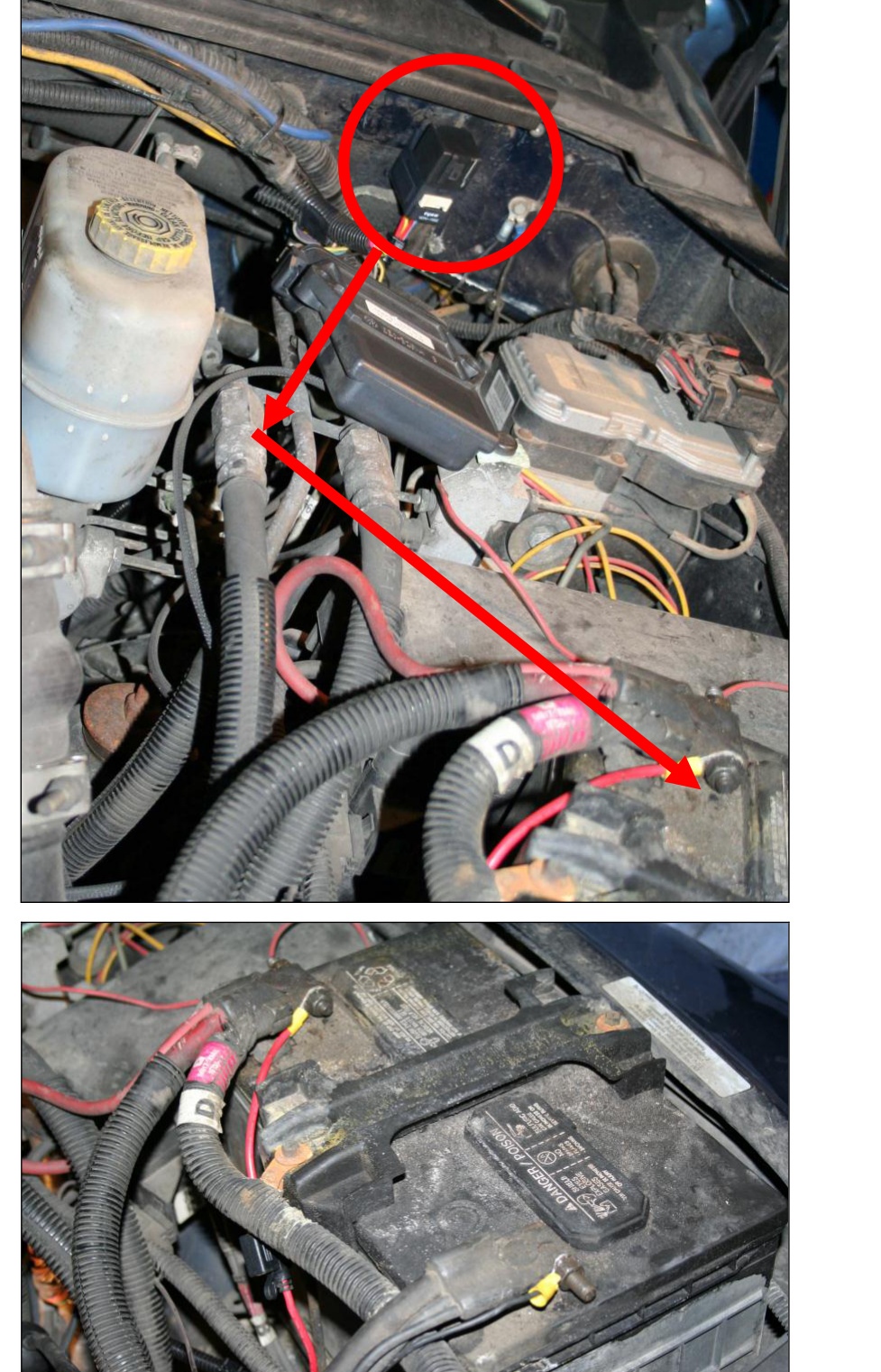
- Lay out the wiring harness so that it can be plugged into the stock fuel-pump harness, plug into the new FlowMAX fuel pump, and place the positive and negative terminals in their approximate routing. Once the routing paths have been chosen and laid out, install the relay to the firewall using the supplied self-tapping screw.
- Attach the wiring with the supplied tie wraps so that it is kept away from hot surfaces and/or moving components. Once the wiring is attached and everything is in place, the positive and negative terminals can be attached to the battery.
- Make certain that all fuel lines and the wiring harness are fixed firmly in place.
- Lower the vehicle and re-install the battery cables.
- Take the truck for a test drive and measure the pump output pressure. The pump pressure should idle at 15–18 psi.
CAUTION: Route and secure all wiring with the supplied tie wraps so it stays clear of hot surfaces and moving components.
Wiring Diagram
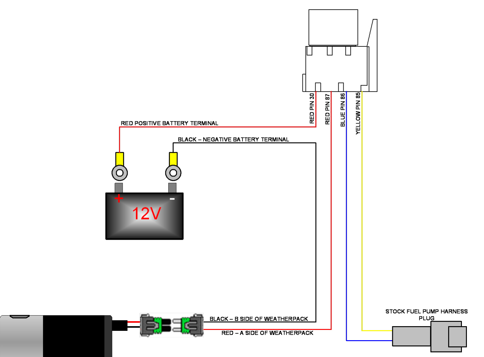
Wire the harness according to the diagram below. The relay connects to the battery (12 V), the FlowMAX pump (via the Weatherpack connectors) and the stock fuel-pump harness plug.
- Red Pin 30 → Red positive battery terminal
- Red Pin 87 → Red – A side of the Weatherpack (pump positive)
- Blue Pin 86 → Stock fuel-pump harness plug
- Yellow Pin 85 → Stock fuel-pump harness plug
- Black – B side of the Weatherpack → Black negative battery terminal
Troubleshooting
If you experience problems, complete the following tests or procedures:
- Clean and re-tighten the battery terminals.
- Ensure there are no crimped or pinched sections of fuel line.
- Change the fuel filter.
- Check that you have at least 12 volts at the electrical connector at the pump.
- Check that the fuse in the supplied harness near the battery terminal is not blown.
- Check that all plugs are securely clipped together.
- Run a hose from a fuel can full of diesel to the pump inlet to see if the pressure changes. If the pressure increases, the problem is a restriction in the line — possibly a clogged fuel screen.