
Installation instructions for the BD performance transmission built for 2008-2010 Ford 6.4L Powerstroke trucks with the 5R110 transmission, available in 2WD and 4WD (part #1064492 / #1064494). The guide covers recommended service intervals and complete removal and installation.
Download the Original PDF Manual
IMPORTANT: Please read all instructions and the warranty disclaimer before beginning installation.
Applications
- 4WD: Part #1064494
- 2WD: Part #1064492
- Fits 2008–2010 Ford 6.4L Powerstroke with the 5R110 transmission.
Service Intervals
- First service: at 1,000 km (621 miles).
- Subsequent service: every 50,000 km (31,069 miles) following the first service, depending on usage.
Pre-Installation
- Before installing your BD transmission you must flush the transmission coolers using a backflow heated transmission flushing machine.
- If the transmission you are removing failed, or has an excessive amount of debris in the pan, you should replace the transmission cooler and check-valve assembly.
NOTE: Failure to flush the transmission coolers may void your warranty.
Fluids & Lubricants
- Automatic transmission fluid: Motorcraft® MERCON® LV (XT-10-QLV) — specification MERCON® LV.
- Multi-purpose grease: XG-4 and/or XL-5 — specification ESB-M1C93-B.
Torque Specifications
- Transmission fluid drain plug: 18 Nm (159 lb-in)
- Transmission-to-engine bolts (9): 47 Nm (35 ft-lbs)
- Torque converter-to-flexplate nuts (8): 48 Nm (35 ft-lbs)
- Steering damper-to-frame bolt and nut: 103 Nm (76 ft-lbs)
- Front & rear transmission fluid cooler tubes: 40 Nm (30 ft-lbs)
- Transmission insulator and retainer housing bolts: 103 Nm (76 ft-lbs)
- Transmission insulator stud (if required): 75 Nm (55 ft-lbs)
- Transmission vehicle harness connector bolt: 5 Nm (44 lb-in)
- Selector lever cable housing bracket bolts: 48 Nm (35 ft-lbs)
Transmission Removal
- With the vehicle in neutral, position it on a hoist.
NOTE: If transmission disassembly is required, drain the transmission fluid.
- 4WD: remove the transfer case assembly. 2WD: remove the driveshaft.
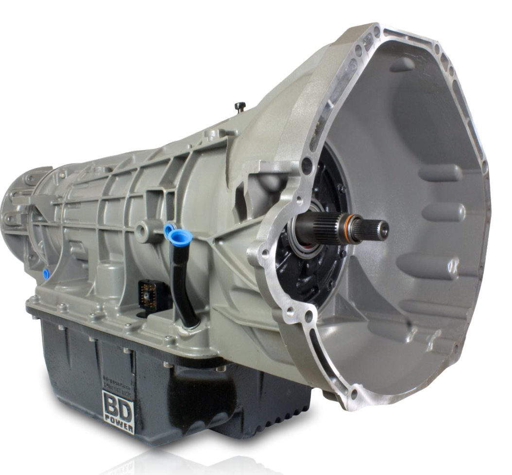
- Remove the transmission pan drain plug and allow the transmission fluid to drain.
- Install the transmission fluid drain plug. Tighten to 18 Nm (159 lb-in).
- Install a suitable high-lift transmission jack.
- Remove the transmission support cross member.
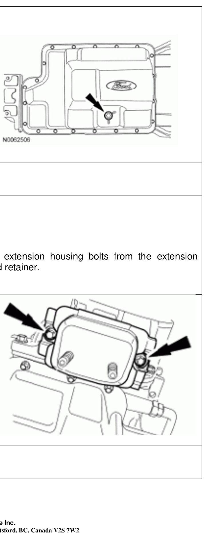
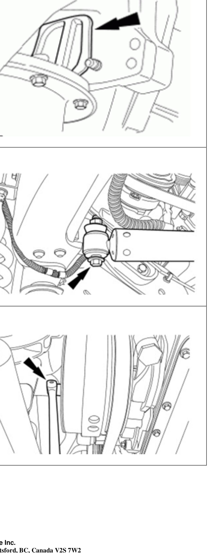
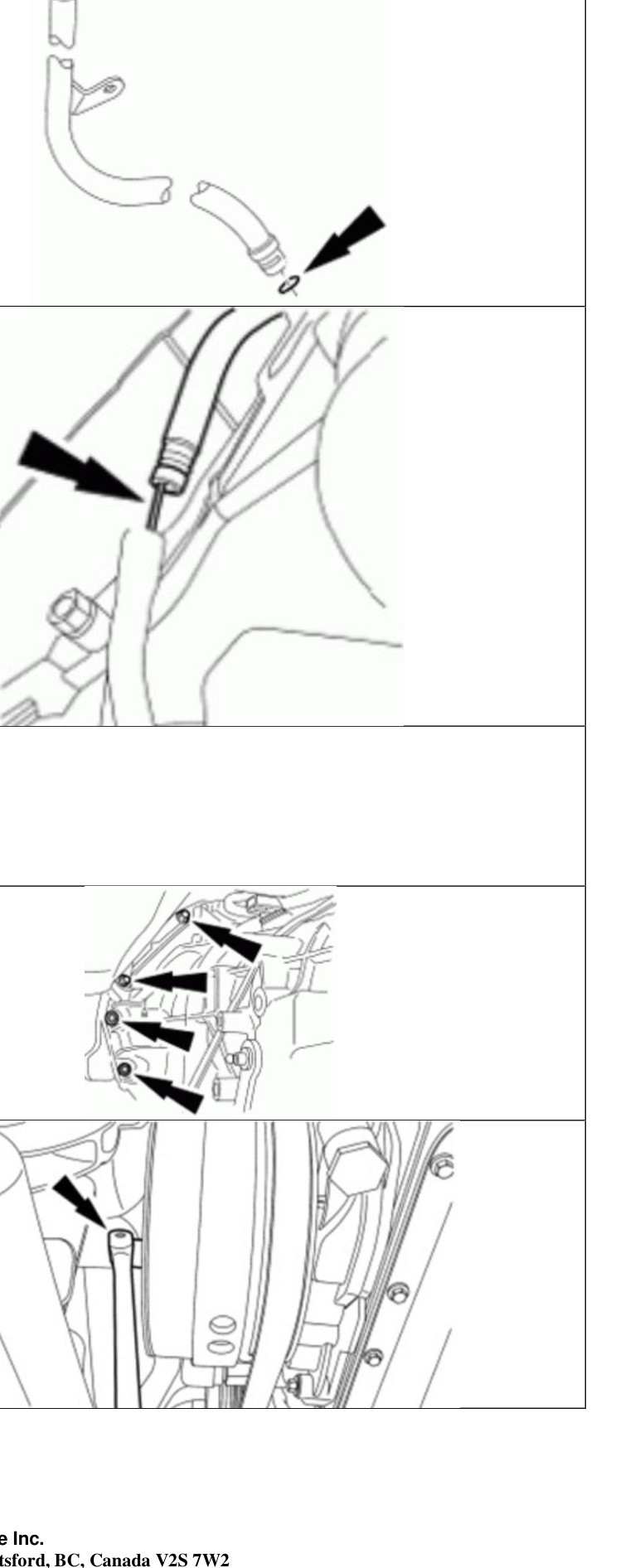
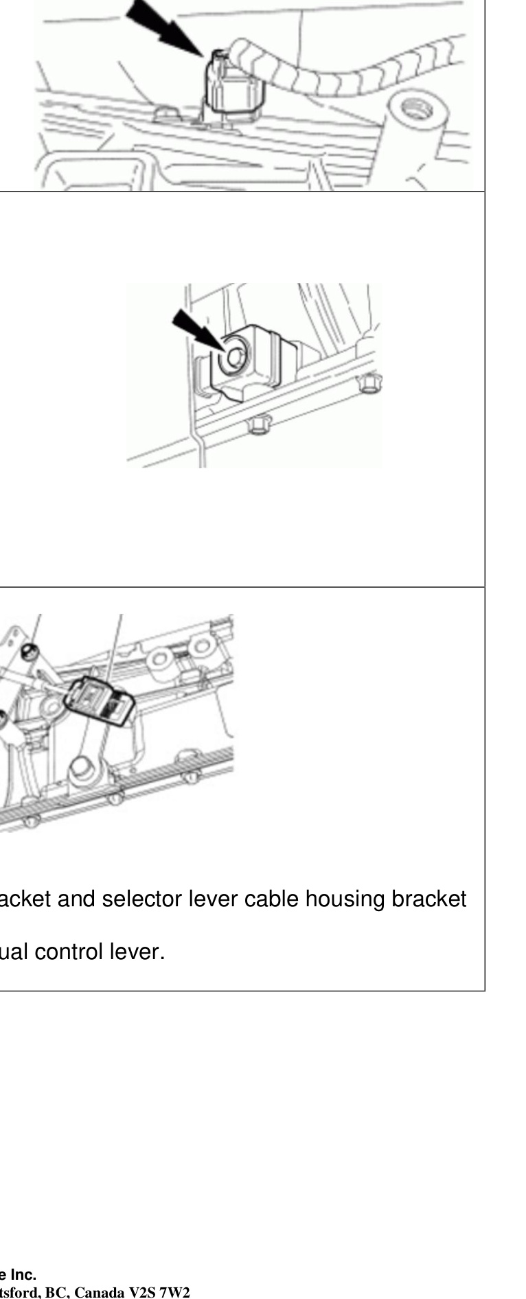
- Remove the transmission insulator and retainer extension-housing bolts from the extension housing, then remove the transmission insulator and retainer.
- Remove the selector lever cable. Disconnect the selector lever cable from the manual control lever. Remove the selector lever cable bracket bolts and position the selector lever cable and bracket aside.
- Loosen the bolt and disconnect the transmission vehicle harness connector.
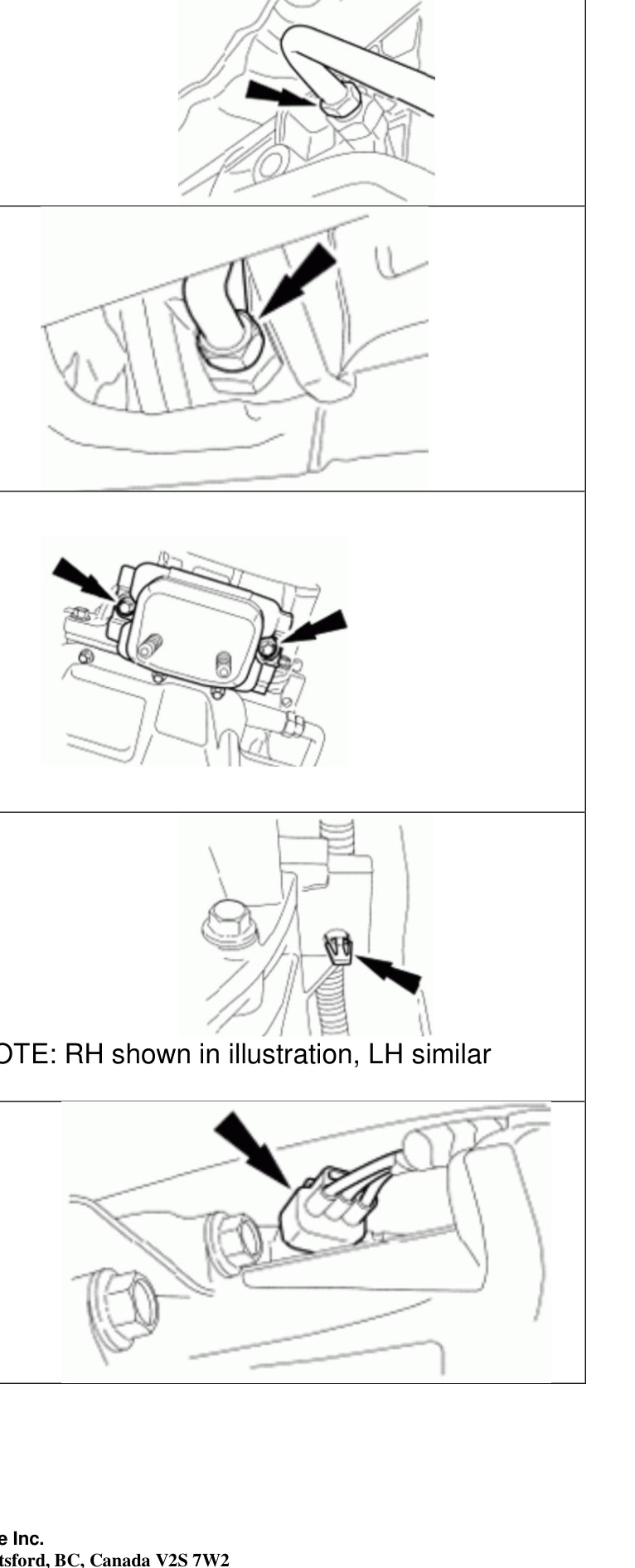
- Disconnect the output shaft speed (OSS) sensor.
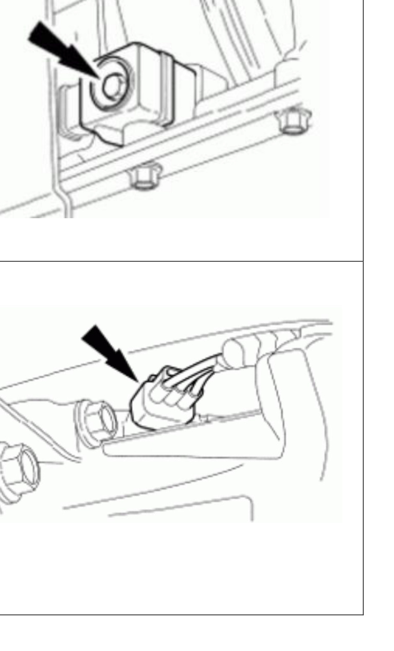
- Disconnect the turbine shaft speed (TSS) / intermediate shaft speed sensor.
- Disconnect the RH and LH wire harness from the side of the transmission.
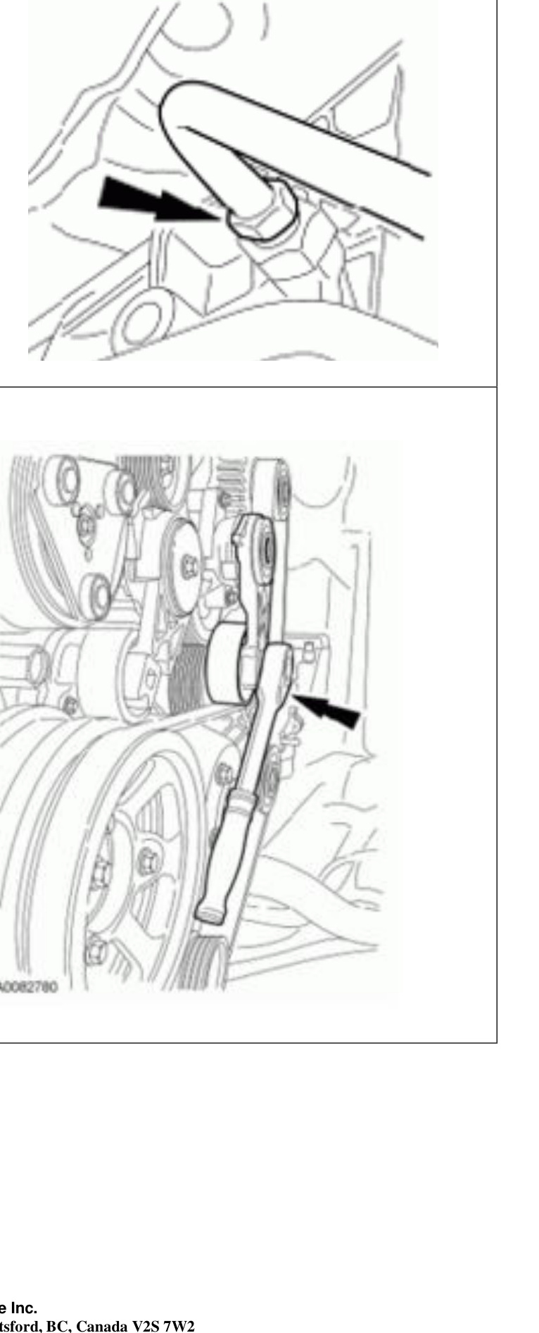
- While holding the case fitting, remove the rear transmission cooler tube.
NOTE: RH shown in illustration; LH similar.
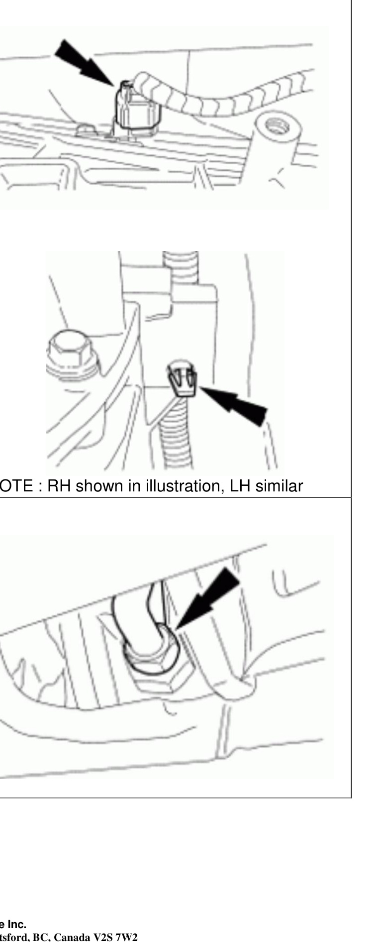
- While holding the case fitting, remove the front transmission cooler tube.
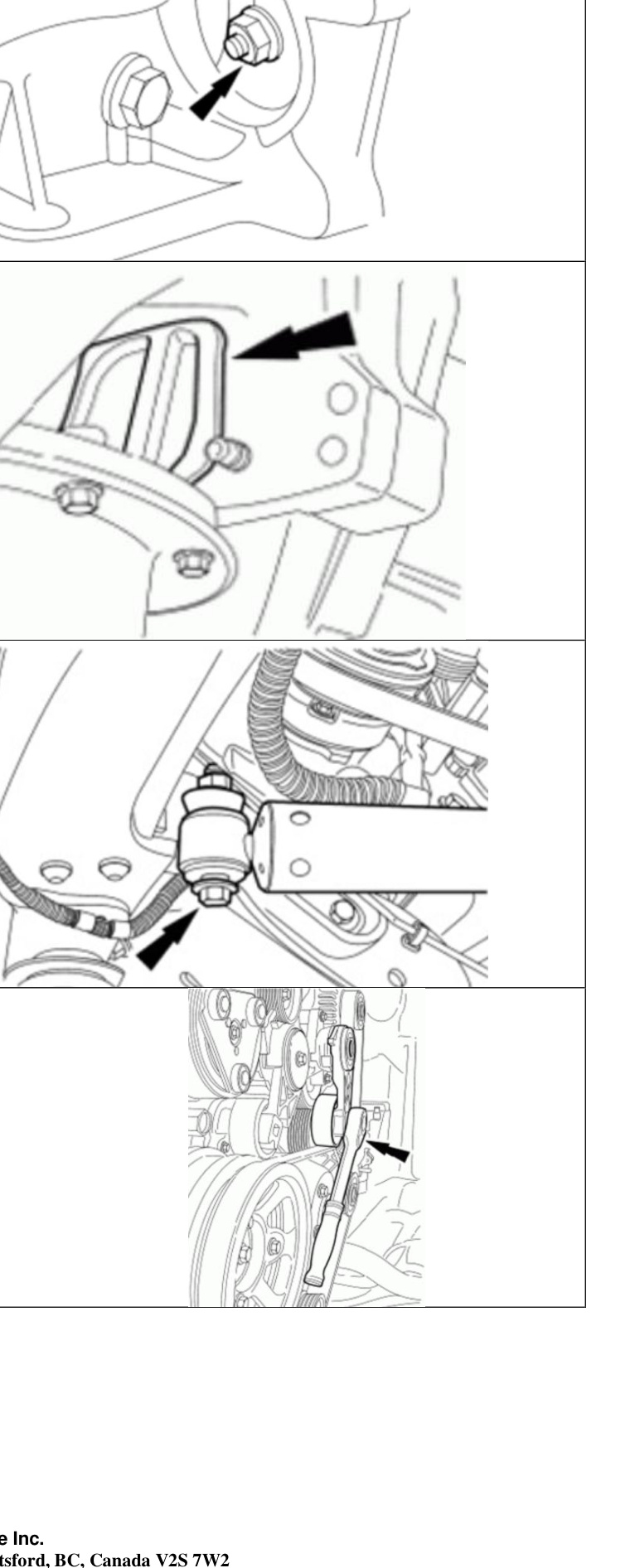
- If equipped with dual generators, rotate the tensioner and remove the outer accessory drive belt from the crankshaft pulley.
NOTE: You will need to remove both front and rear case fittings from the stock transmission, then install them into the BD transmission.
- Remove the cylinder block opening cover to gain access to the torque converter-to-flexplate nuts.
- Remove the steering damper-to-frame bolt and nut, and position the steering damper aside.
- Using a suitable tool, rotate the crankshaft pulley to gain access to the torque converter-to-flexplate nuts.
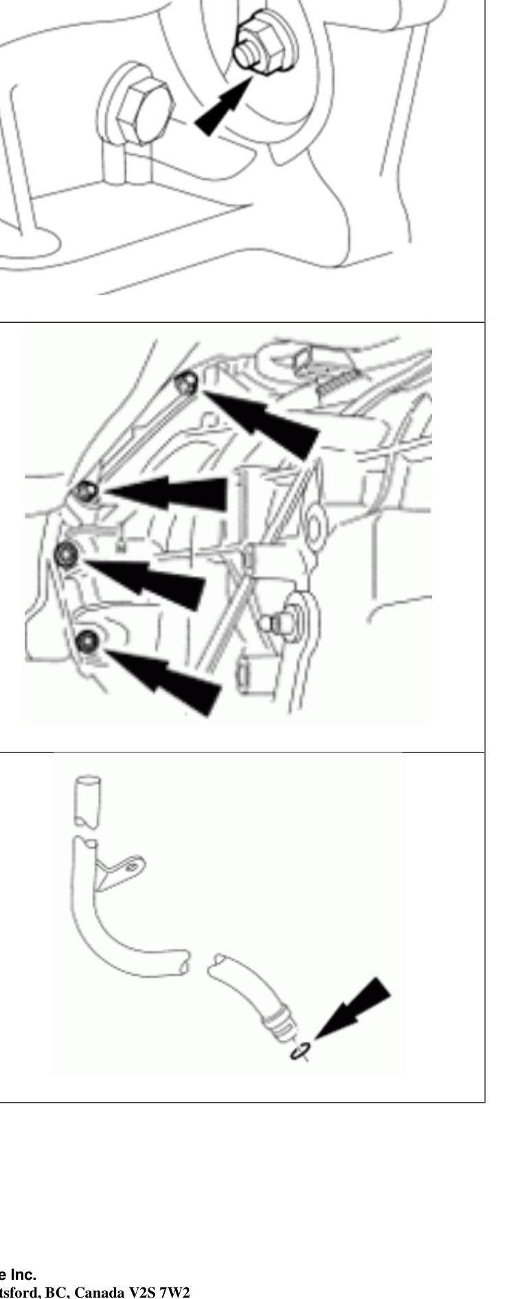
- Remove and discard the 8 torque converter-to-flexplate nuts.
- Remove the 9 transmission-to-engine mounting bolts.
- Carefully lower the transmission assembly.
- Carefully remove the torque converter by pulling it forward out of the bell housing.
- Remove and discard the transmission fluid filler tube O-ring.
- Carry out the transmission fluid cooler back-flushing and cleaning procedure.
- For vehicles equipped with a power take-off (PTO) assembly, the PTO assembly must be flushed and cleaned to remove any foreign material prior to installing the transmission.
WARNING: Failure to remove foreign material from the PTO assembly may result in subsequent transmission concerns.
Transmission Installation
NOTE: The transmission cooler must be thoroughly flushed with a transmission cooler flushing machine.
NOTE: If the transmission had a significant failure, installation of a new oil-to-air cooler and radiator is highly recommended.
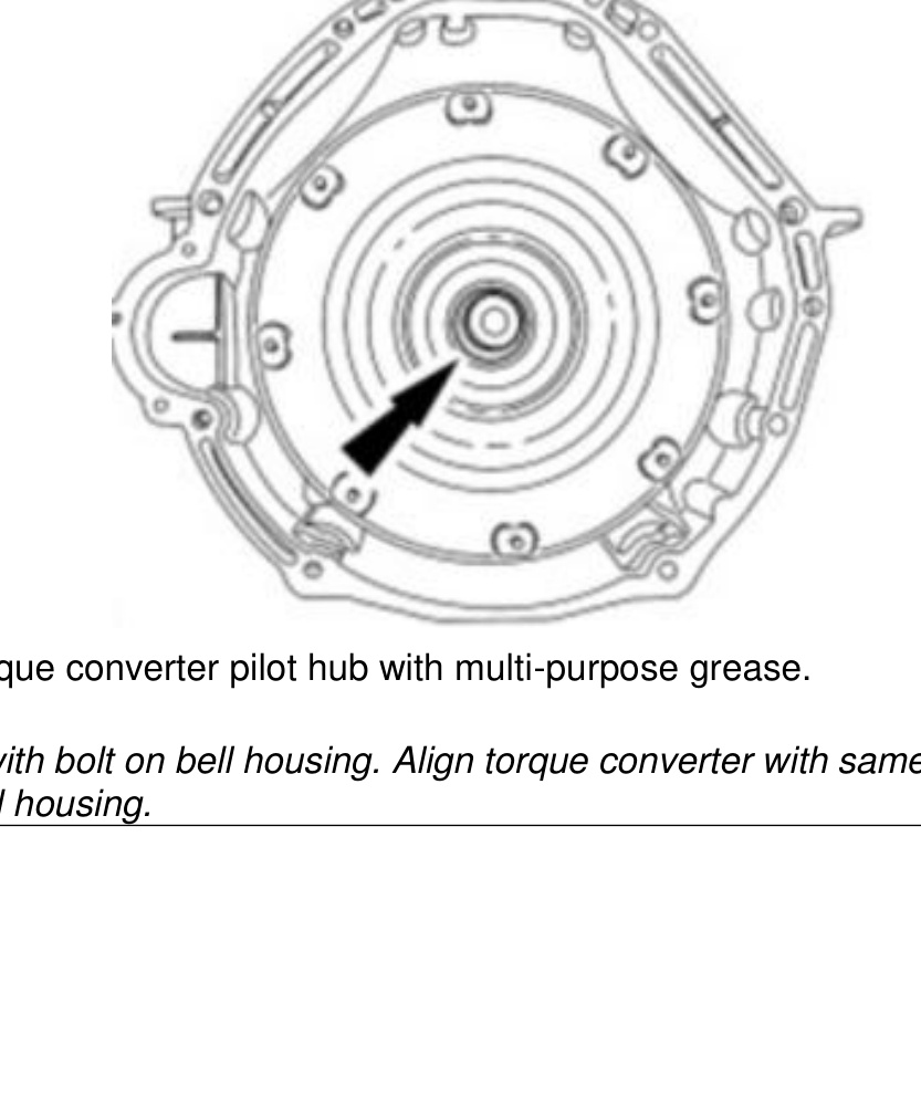
CAUTION: Prior to installation of the transmission, the torque converter pilot hub must be lubricated, or damage to the torque converter or the engine crankshaft can occur.
Lubricate the torque converter hub and install the torque converter onto the input shaft. Rotate and wiggle the converter to engage the splines and be sure it is fully engaged onto the input shaft.
- Lubricate the torque converter pilot hub with multi-purpose grease.
- Align the flex plate with the bolt on the bell housing. Align the torque converter with the same hole on the transmission bell housing.
- Install a new transmission fluid filler tube O-ring.
- Position the transmission in place. While raising the transmission up into the engine compartment, align the transmission fluid filler tube with the stub tube on the transmission, using the transmission fluid level indicator as a guide.
- While installing the transmission to the engine, align the torque converter studs with the mounting holes in the flexplate.
- Install the 9 transmission-to-engine bolts. Tighten to 47 Nm (35 ft-lbs).
- Using a suitable tool, rotate the crankshaft pulley to gain access to the torque converter-to-flexplate nuts.
- Install the 8 supplied torque converter-to-flexplate nuts. Tighten to 48 Nm (35 ft-lbs).
- Install the cylinder block opening cover.
- Position the steering damper and install the steering damper-to-frame bolt and nut. Tighten to 103 Nm (76 ft-lbs).
- If equipped with dual generators, rotate the tensioner and install the outer accessory drive belt onto the crankshaft pulley.
- Install the front transmission fluid cooler tube. Tighten to 40 Nm (30 ft-lbs).
- Install the rear transmission fluid cooler tube. Tighten to 40 Nm (30 ft-lbs).
- Install the transmission insulator and retainer housing bolts. Tighten to 103 Nm (76 ft-lbs).
- If required, install a new transmission insulator stud. Tighten to 75 Nm (55 ft-lbs).
- Install the transmission support cross member.
- Connect the RH and LH wiring harness to the side of the transmission.
- Connect the output shaft speed sensor.
NOTE: RH shown in illustration; LH similar.
- Connect the turbine shaft speed / intermediate shaft speed sensor.
- Connect the transmission vehicle harness connector. Tighten to 5 Nm (44 lb-in).
- Connect the selector lever cable. Install the selector lever cable housing bracket and bracket bolts; tighten to 48 Nm (35 ft-lbs). Install the selector lever cable to the manual control lever.
NOTE: If the vehicle is equipped with a power take-off (PTO) unit, all or part of the PTO unit will need to be installed.
CAUTION: To prevent selector lever cable damage, do not apply force to the selector lever cable assembly between the manual control lever and the selector lever cable bracket.
- 4WD vehicles: install the transfer case. RWD vehicles: install the rear driveshaft.
- Follow the in-line transmission fluid filter guidelines below.
In-Line Transmission Fluid Filter Guidelines
- If the transmission was overhauled and the vehicle was equipped with an in-line transmission fluid filter, install a new in-line transmission fluid filter.
- If the transmission was overhauled and the vehicle was not equipped with the in-line transmission fluid filter, install a new in-line transmission fluid filter.
- If the transmission is being installed for a non-internal repair, do not install an in-line transmission fluid filter or filter kit.
- If installing a new or a Ford-authorized remanufactured transmission, install an in-line transmission fluid filter.
- We recommend using the FT-184 filter, available at your local Ford dealer.
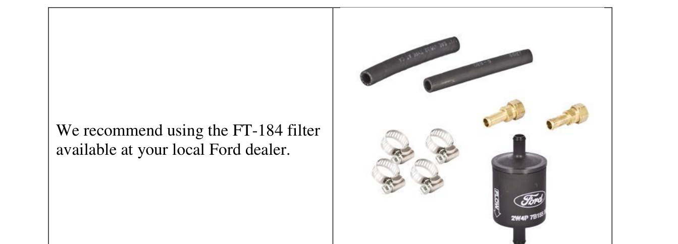
- Prior to lowering the vehicle, install a new in-line transmission fluid filter or a transmission fluid filter kit.
- With the installation of an overhauled or remanufactured transmission, the transmission fluid cooler tubes must be cleaned and back-flushed, and then the transmission fluid flow verified, to prevent repeat repairs.
- Adjust the selector lever cable. Verify that the vehicle starts in PARK and NEUTRAL and that the reverse lamps illuminate in REVERSE.
- With the engine running and the transmission at normal operating temperature 66–77°C (150–170°F), check and adjust the transmission fluid level and check for leaks. If transmission fluid is needed, add it in increments of 0.24 L (0.5 pt) until the correct level is achieved (the fluid should be in the hot-range cross-hatched area of the transmission fluid level indicator).
- For vehicles equipped with a PTO assembly, the PTO assembly must be flushed and cleaned to remove any foreign material prior to installing the transmission.
WARNING: Failure to remove foreign material from the PTO assembly may result in subsequent transmission concerns.