
Installation instructions for the BD remote-mount air exhaust brake fitted to 2003-2005 GMC Duramax C4500/5500 trucks (part #1023310 and #1023311). The kit is available with or without a BD air compressor and adds powerful exhaust braking for safer towing and descents.
Download the Original PDF Manual
Thank you for purchasing a BD Engine Exhaust Brake. Before you begin, check that your kit contains all of the items listed below for your part number.
Kit Contents
1023310 — GMC C4500/5500 Brake (without new Air Compressor)
- 1 × Exhaust Brake valve (1127038)
- 1 × Adapter Pipe (1100300)
- 2 × Marmon Clamp (1100404)
- 2 × 3″ Exhaust Seal Clamp (1100730)
- 1 × Control Kit (1220010)
- 1 × Air snorkel kit, with tubing (1220100)
- 1 × Regulator Kit (1220046)
- 1 × Solenoid Assy. (1220048-C)
1023311 — GMC C4500/5500 Brake (with BD Compressor)
- 1 × Exhaust Brake valve (1127038)
- 2 × Adapter Pipe (1100300)
- 2 × Marmon Clamp (1100404)
- 1 × 3″ Exhaust Seal Clamp (1100730)
- 1 × Control Kit (1220010)
- 1 × Air snorkel kit, with tubing (1220110)
- 1 × Solenoid Assy. (1220048-C)
- 1 × BD Air Compressor kit, with regulator (1030116)
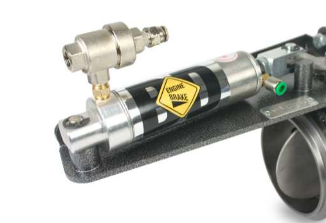
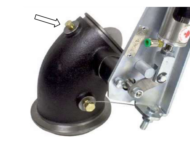
Exhaust Brake Valve Installation
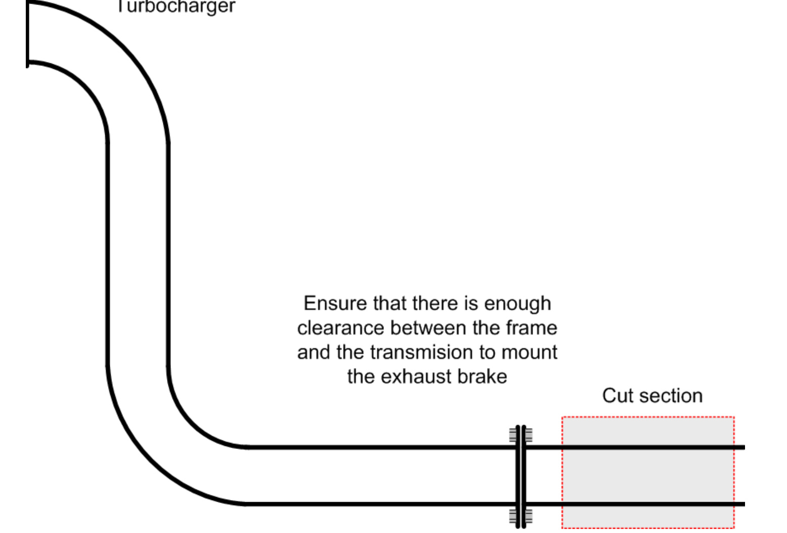
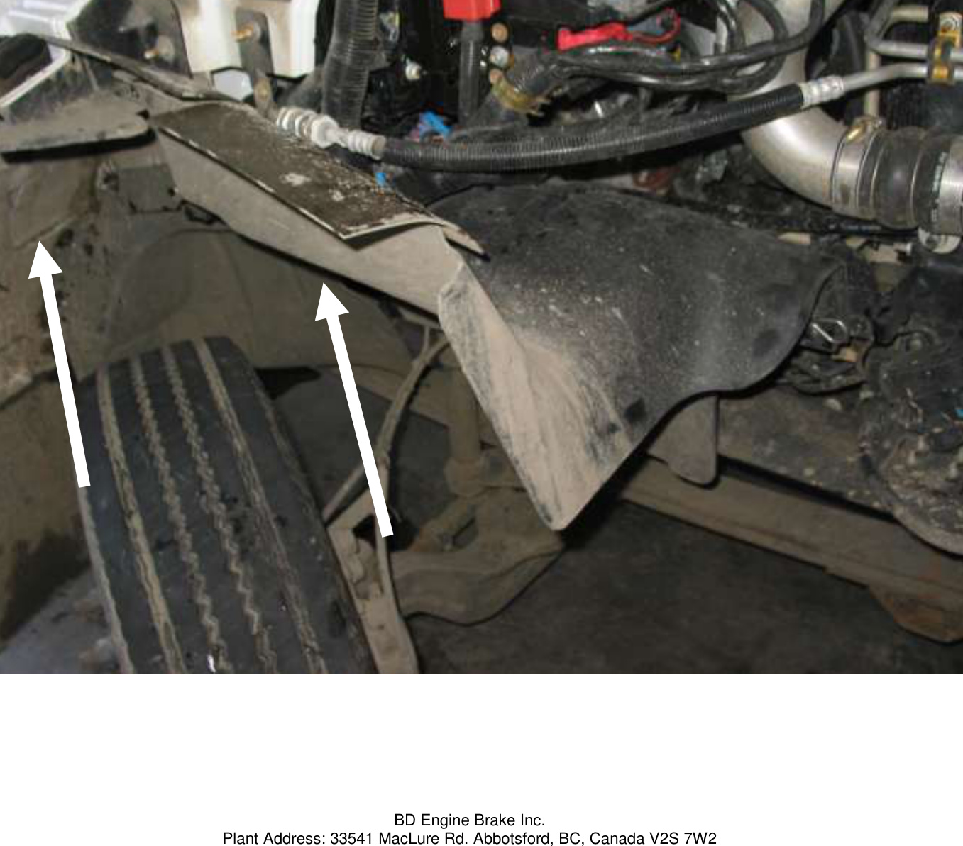
Locate the turbo down-pipe from underneath the vehicle. You will need a 7-1/4″ section of pipe to mount the exhaust brake assembly.
- Check clearances between the brake and the transmission and frame rail before cutting.
- Mark the desired cut section and remove the pipe for welding.
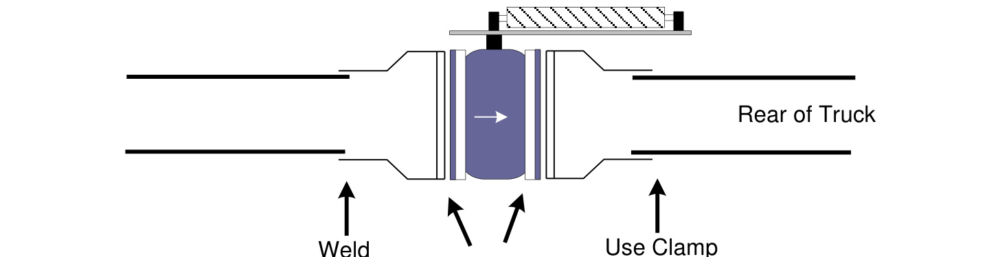
- The exhaust adapter closest to the turbo must be welded. The rear adapter can be secured using the stainless steel band clamp.
- Ensure the brake is installed in the correct flow direction — there is an arrow molded into the casting on the valve assembly indicating the correct exhaust flow path.
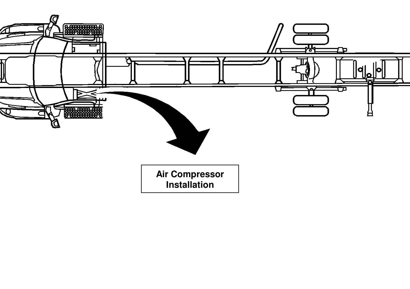
Air Compressor Installation (If Applicable)
NOTE: If your vehicle already has a factory-mounted air compressor, skip this section and move to Air Regulator Installation below.
If you are installing the BD air compressor with this kit, mount the air compressor underneath the cab on the driver's side.
- Select a position that will keep road debris and water away from the unit.
- Use the supplied mounting hardware to secure the air compressor assembly to the frame rail underneath the driver's cab.
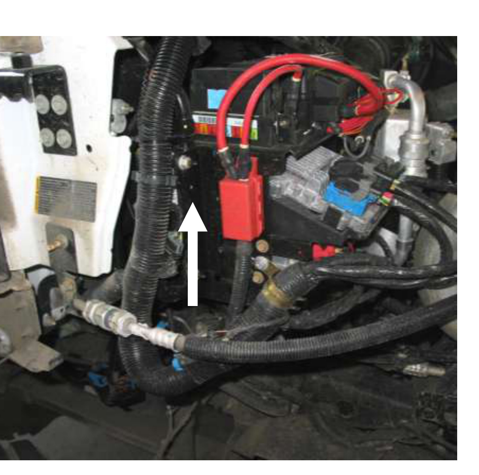
- Connect the power and ground for the wiring harness to the battery on the passenger side, or to the power point and ground underneath the hood.
Air Regulator Installation
NOTE: If you installed the BD Air Compressor kit, skip this step — its regulator is already included.
For vehicles equipped with a factory-installed air compressor, you will need to “tee” into the air tank supply line and route it into the air regulator “IN” port.
- Install the air regulator assembly in a clean environment, close to the factory air tank. Keep the location easily accessible — you will have to adjust the regulator later.
- Run the nylon tubing from the air tank tee into the regulator “IN” port. Use the supplied quick-connect fittings.
Air Solenoid Valve Installation
- Mount the air solenoid on the inside of the frame rail, just across from the exhaust brake.
- Clean a section of the frame for the ground point, then use the supplied hardware to bolt the solenoid to an existing hole in the frame rail.
- Route the supplied nylon tubing from the “IN” port of the solenoid valve to the previously installed air regulator “OUT” port.
- The “CYL” (or “OUT”) port on the valve goes to the quick connector on the exhaust brake valve cylinder you installed earlier.
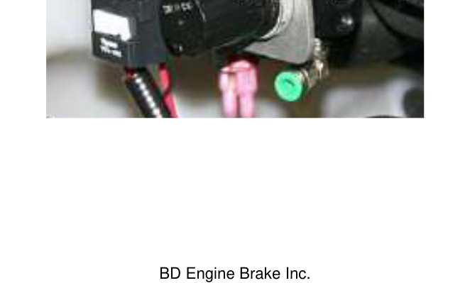
- The solenoid kit also includes a small wiring harness with a noise-suppression diode. Install it on the electrical connectors of the solenoid valve.
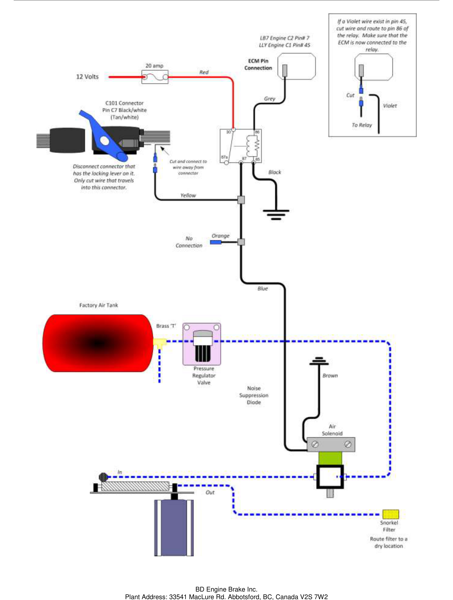
Vehicle Wiring
You will need to remove both passenger-side fender shields to access the ECM. Follow the section that matches your engine.
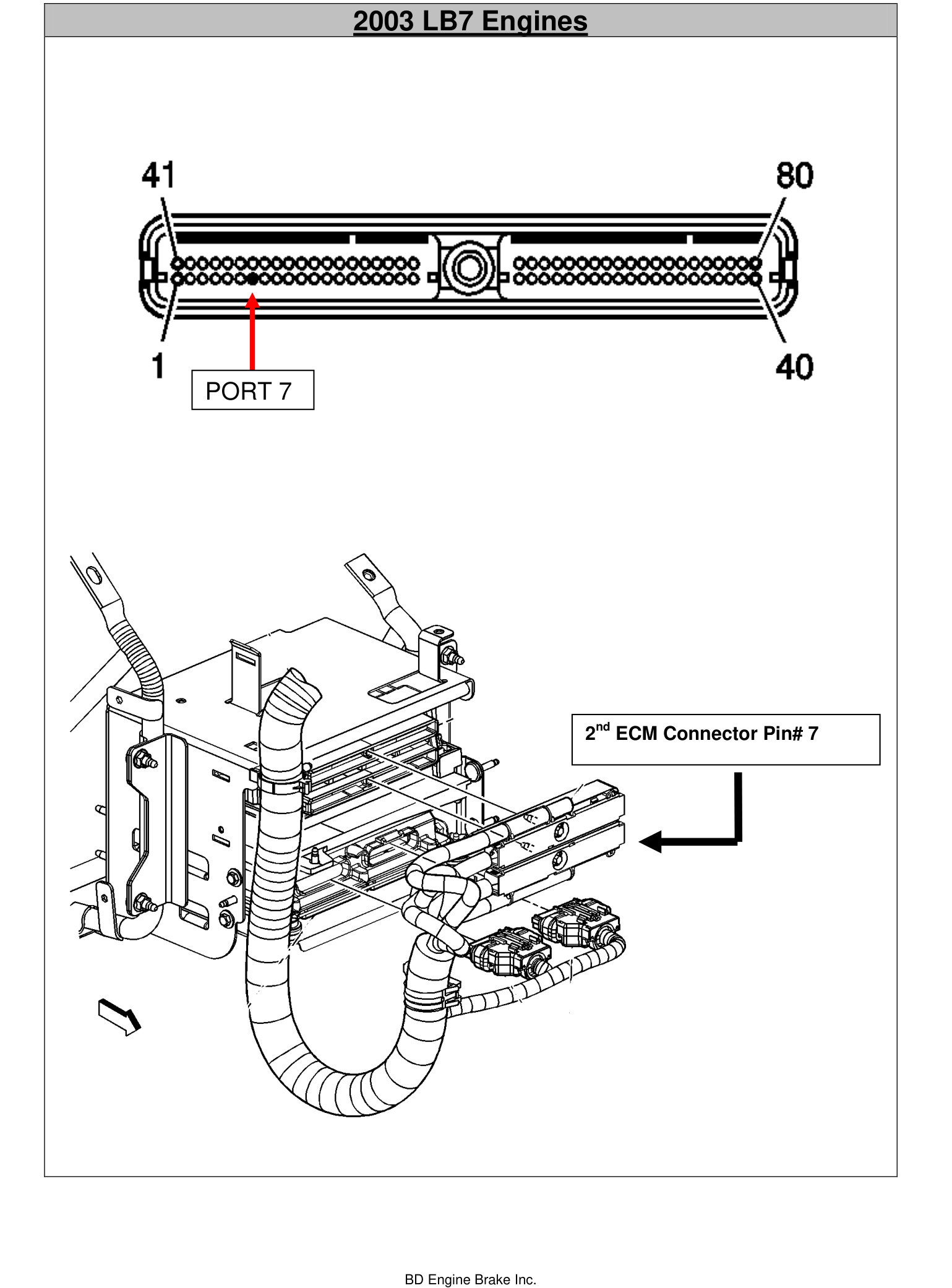
LB7 Engine (2003)
- Locate the vehicle's ECM and remove the second (lower) ECM connector.
- Connect the supplied ECM pin connector to the supplied 18 AWG grey wire. The LB7 motor uses the longer pin terminal (two pins are included — one for LB7, one for LLY).
- Insert the pin connector into port #7 of the ECM connector. You may need to poke a hole through the weather seal to ease installation. There will be a plastic pin in that location which must be removed first.
- Reconnect the lower ECM connector.
- Route the pin-and-wire assembly to connector 86 of the relay assembly.
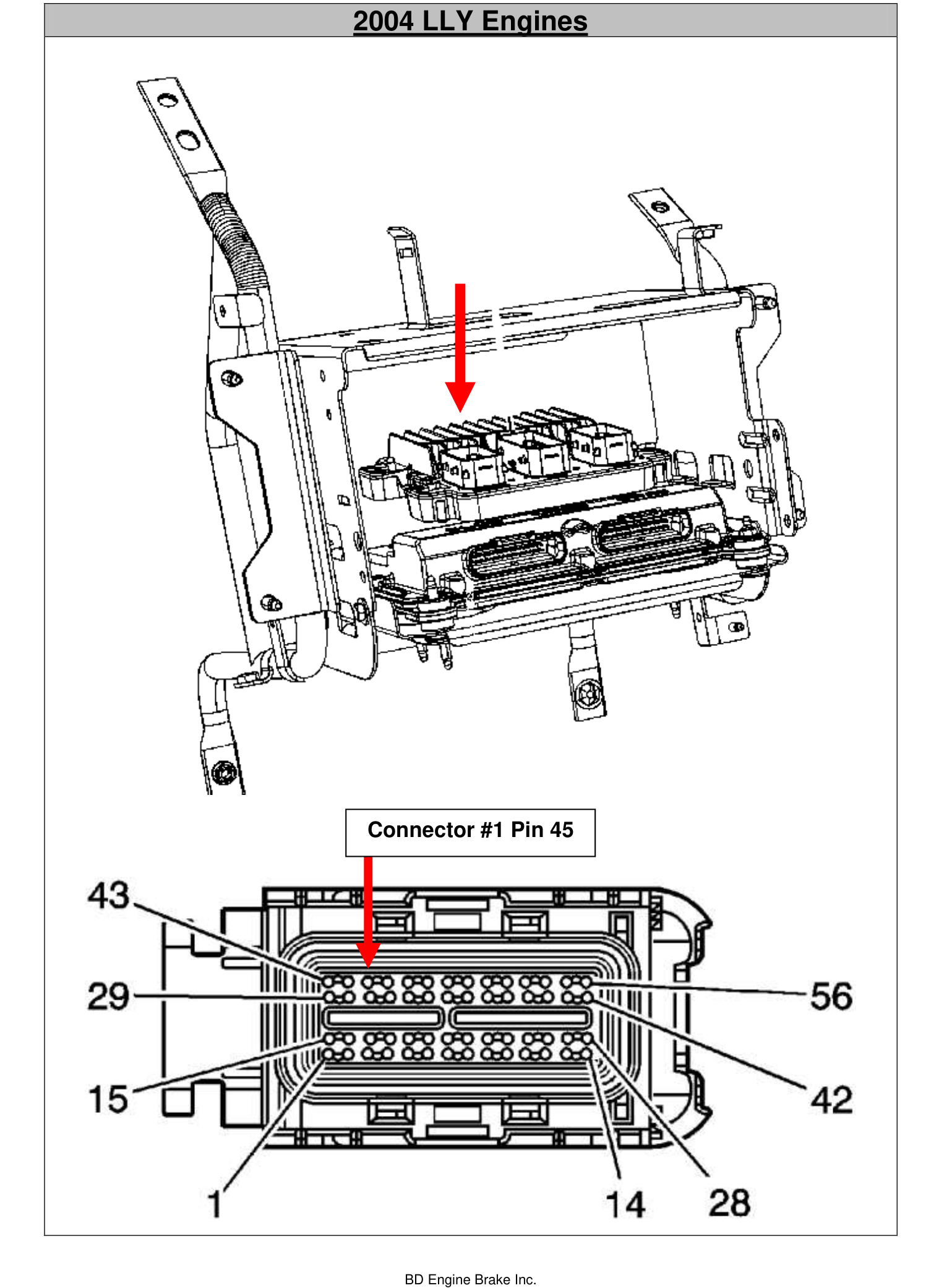
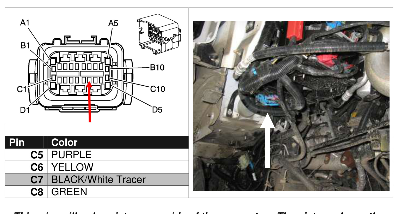
LLY Engine (2004-2005)
- Locate the vehicle's ECM and remove the first ECM connector.
- Connect the supplied ECM pin connector to the supplied 18 AWG grey wire. The LLY uses the short pin terminal.
- Insert the short pin connector into port #45 of the ECM connector. You may need to poke a hole through the weather seal — on some applications you may first need to remove the connector's lock pin. Remove any plastic blank pin in that location before installing the ECM pin.
- On some LLY models you will find a PURPLE wire in pin location 45. If so, cut this wire and connect the supplied relay harness's grey wire to the ECM's purple wire; leave the other side of the cut wire floating.
- Reconnect the lower ECM connector.
- Route the pin-and-wire assembly to connector 86 of the relay assembly.
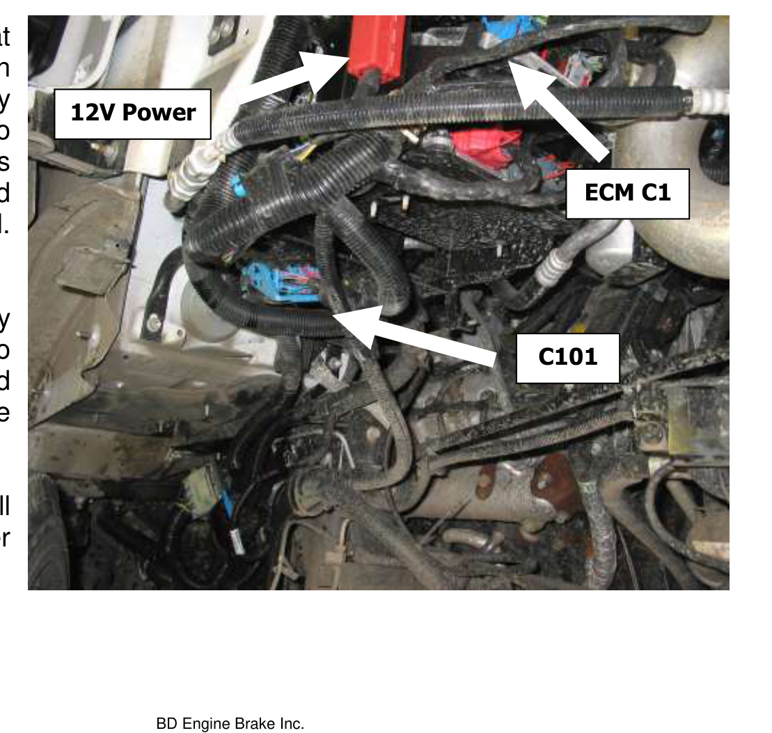
- Install the supplied relay harness to the side of the ECM support bracket using the supplied sheet-metal screw.
- Connect the fused red wire lead to a 12V battery red quick-access point. This wire travels to pin 30 of the relay assembly.
C101 Connector (C7) — Brake Signal Wire
Just below the ECM and TCM, locate the outer 30-pin weather-pack connector C101. This connector has a locking blue latch — separate the two halves for easy access.
- At pin C7 find the black-with-white-tracer wire (or tan-with-white-tracer). This wire exists on only one side of the connector — the side with the locking tab.
- Cut this wire and attach the supplied BD wiring harness to it with the supplied butt connector, joining to the wiring-harness end, not the connector end.
- This new connection at C7 travels to the relay assembly and also down to the brass solenoid valve mounted on the frame rail.
- Connect pin 85 of the relay to a clean, solid ground using the black wire provided.
- Re-install the two inner fender shields.
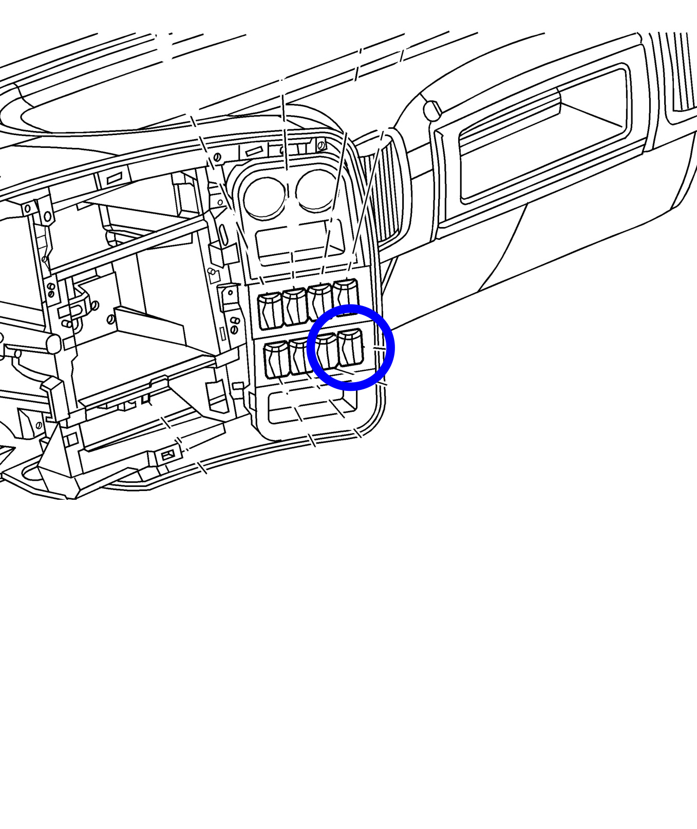
In-Cab Installation
- Remove the dash panel to gain access to the accessory switches.
- Install the GM switch (15010301) into an empty slot. The wiring is already pre-installed to the bottom-right switch location — locate the Light Green wire.
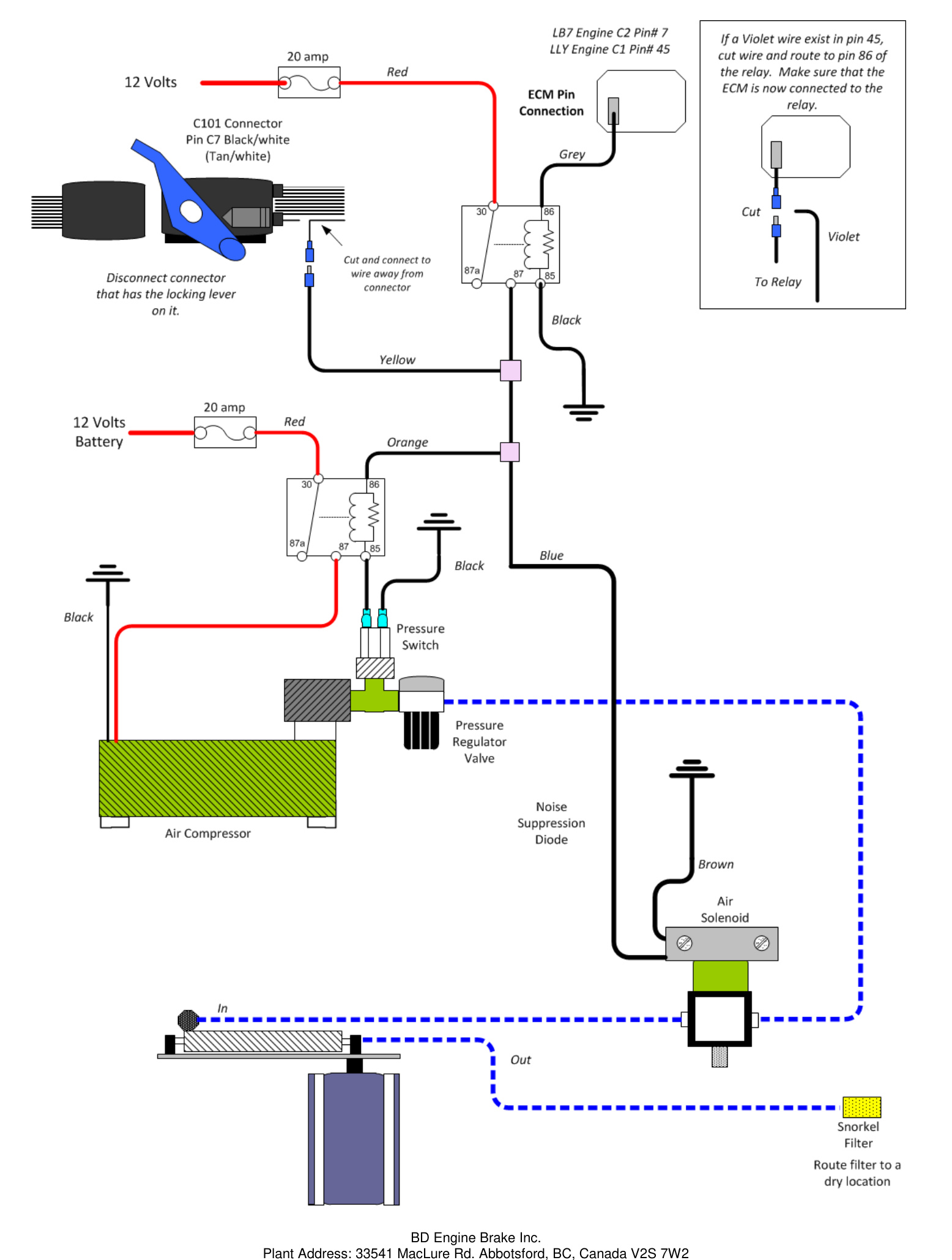
System Overview Diagrams
Use the overview diagram that matches your configuration to confirm all air-line and wiring connections.
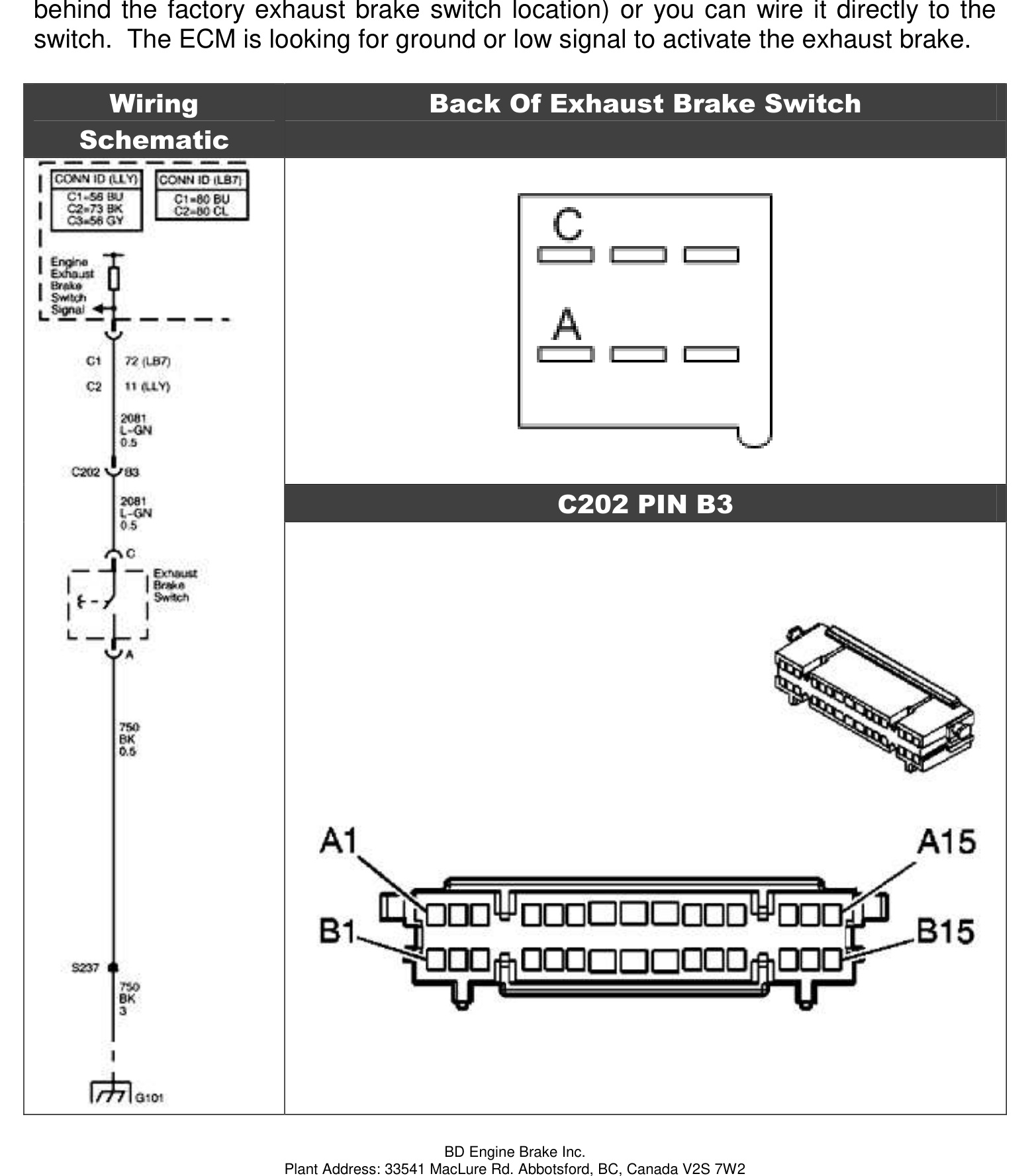
LLY Exhaust Brake Switch Addendum
NOTE: Some LLY C4500/5500 models were not pre-wired from GM to accept the factory exhaust brake switch.
To check, locate Connector #2 of the ECM and look for a Light Green wire on Pin #11. If it exists, the vehicle is pre-wired. If not:
- Use the extra LLY ECM pin (P/N 15356827) and insert it into Pin #11 of the C2 connection of the ECM.
- Wire it back to the factory switch — either to Pin B3 of the C202 connector (located just behind the factory exhaust brake switch) or directly to the switch.
The ECM is looking for ground (a low signal) to activate the exhaust brake.
Maintenance & Troubleshooting
- To extend the life of the valve assembly, do not operate the vehicle for extended periods without activating the brake. We recommend daily use — switching the brake on and off a couple of times a day prevents the butterfly from sticking due to carbon or rust build-up.
- Inspect the hoses, wires, fittings and clamps regularly for deterioration, damage or leaks.
- Periodically clean the filter on the air compressor. When cleaning the engine, cover the compressor filter to prevent moisture from entering it.
- To troubleshoot, follow the diagrams in this manual: trace hoses and wiring, check continuity through electrical components, and look for any disconnected lines.
Operating Guidelines
An exhaust brake increases the driveline drag of the vehicle to help slow it down without using the hydraulic brakes — reducing heat, wear and the risk of brake fade on hills, long grades, off-ramps and corners. By reducing hydraulic brake use in these situations, you save your service brakes for when you really need them.
- The BD Exhaust Brake helps maintain a controlled speed on downward grades and slows the vehicle for turns or exit ramps.
- When the switch is ON, the valve activates every time the driver lifts off the throttle, and opens again when the throttle is reapplied.
- For the best retarding force, select a gear that lets you maintain a constant speed downhill — generally the same gear you would use to climb the same grade.
- Automatic transmissions with lock-up clutches achieve the best retarding force with a clutch-control device (e.g. AutoLoc).
WARNING: The exhaust brake is not a substitute for your hydraulic brakes and cannot be used as a parking brake or a service brake to bring the vehicle to a complete stop. It is designed to operate at idle throttle — do not use it with cruise control or to aid gear shifting, as this could damage the engine and/or the exhaust brake.
Exhaust Backpressure Testing
NOTE: The brake stop-bolt and regulator are preset at the factory and should not normally need adjustment. We recommend purchasing the BD pressure gauge kit #1030050. You only need to measure the exhaust backpressure (at the test port on the cast valve), not the air pressure in the system.
Idle Pressure Test
With the BD brake engaged and the engine at idle, check the exhaust backpressure at the test port on the brake valve.
- Below 13 psi at idle: the most common cause is an exhaust leak at a clamp joint or weld. Apply the brake and have a helper look for soot trails or a visible leak. Other causes include an exhaust manifold leak, turbocharger gasket leak, turbocharger problem or an EGR issue.
- Greater than 25 psi: adjust the stop bolt — loosen the jam nut and lengthen the stop bolt toward the actuator to shorten the stroke. Turn only 1/4 rotation at a time, re-secure the jam nut and retest.
IMPORTANT: We generally do not recommend adjusting the stop bolt — please consult BD before doing so, as it may void your warranty. Over the next two weeks, idle backpressure may rise as carbon builds up inside the brake housing and on the butterfly; the stop bolt may need re-adjusting to compensate.
Off-Idle Pressure Test & Adjustment
Your BD exhaust brake is a variable-orifice design, so at higher RPM the brake lever does not rest on the stop bolt. Off-idle backpressure is set with the air pressure regulator.
- Secure your pressure gauge where you can see it while driving (a long extension hose into the cab through an open window, or clipped under a windshield wiper, works well).
- Get the truck up to speed (a downhill grade or a load helps) and activate the exhaust brake. Note the maximum backpressure — peak is reached at higher RPM (try 3000 RPM in Drive).
- If you cannot reach the target backpressure, first check for exhaust leaks at the clamps, manifolds, feed pipes, the back of the turbo and the down-pipe.
- If all connections are sealed, use the regulator to set the pressure. Small adjustments have a significant effect: turn the regulator clockwise to increase pressure and counter-clockwise to decrease it.
Maximum Back Pressure by Application
- GM/Chevy 6.5 — 35 psi
- GM/Chevy Duramax — 55 psi
- Ford Powerstroke — 45 psi
- Dodge Cummins 1988-98 12V (without 60 lb springs) — 40 psi
- Dodge Cummins 1988-98 12V (with 60 lb springs) — 60 psi
- Dodge Cummins 2002 and newer — 60 psi
HD spring part #1030060.
CAUTION: Do NOT exceed the maximum back pressure value for the exhaust system. Exceeding this pressure will force the exhaust valves open during the intake stroke, which could cause engine damage.