
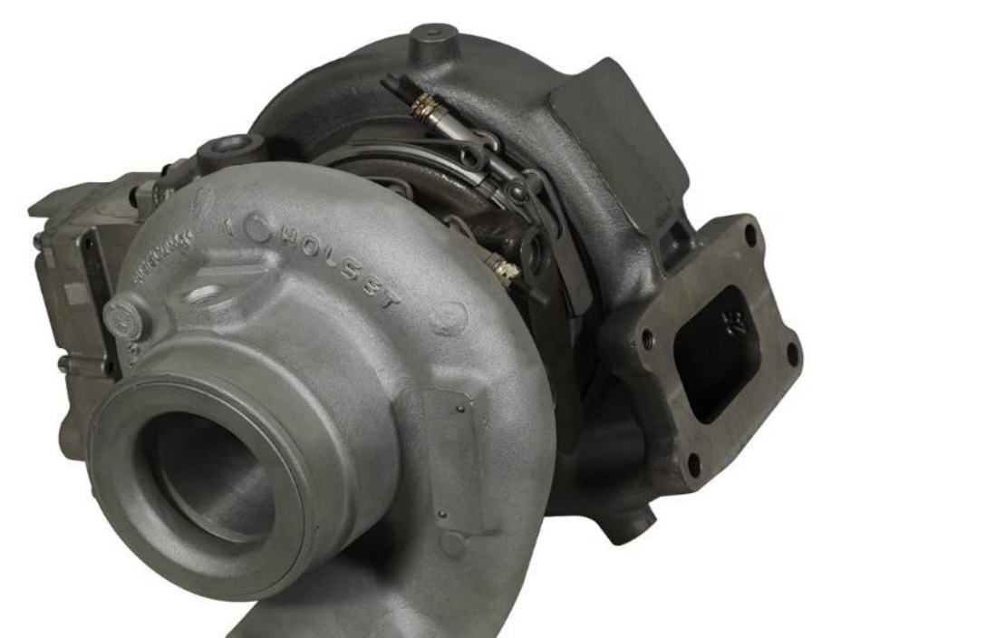
Installation instructions for the BD Screamer performance turbocharger for 2019+ Ram 6.7L Cummins trucks, a CARB-compliant upgrade (EO D-553-14) for 2019–2022 RAM 2500 and 3500. Review the pre-installation checks first—a new turbo will not fix underlying oil supply or contamination problems.
Download the Original PDF Manual
NOTE: Please read all instructions before beginning the installation.
Applications
This kit is available as two part numbers:
- 1045772 — Performance Screamer Turbo
- 1045777 — Stock Remanufactured Turbo
Meets CARB requirements for the following models (EO D-553-14):
- 2019–2022 RAM 2500
- 2019–2022 RAM 3500
Pre-Installation
A new turbocharger will not solve any of the following failures:
- Oil contamination
- Restrictive oil drain and/or oil supply
- Overspeed due to boost leaks
- Exhaust leaks due to faulty seals and/or clamps
IMPORTANT: Turbo overspeed will lead to premature turbo failure. Boost pressure can be used to estimate turbo speed. A restrictive intake or a boost leak will increase turbo speed and cause an overspeed failure. The maximum allowable turbo speed at 3200 RPM is 121,000 RPM, corresponding to a maximum boost of 38 psi.
Pre-Installation Inspection
When replacing a turbocharger, BD recommends the following precautions are taken:
- Replace or clean the air filter.
- Change the engine oil and filter.
- Inspect intake and charge-air-cooler (CAC) passages for debris, and clean if necessary.
In the case of a previous failure, also include the following steps:
- Inspect the CAC for debris, and clean it out if necessary.
- Inspect the engine oil for debris. Flush the system if debris was present.
Ensuring that these steps are followed will prolong the life of your new turbocharger.
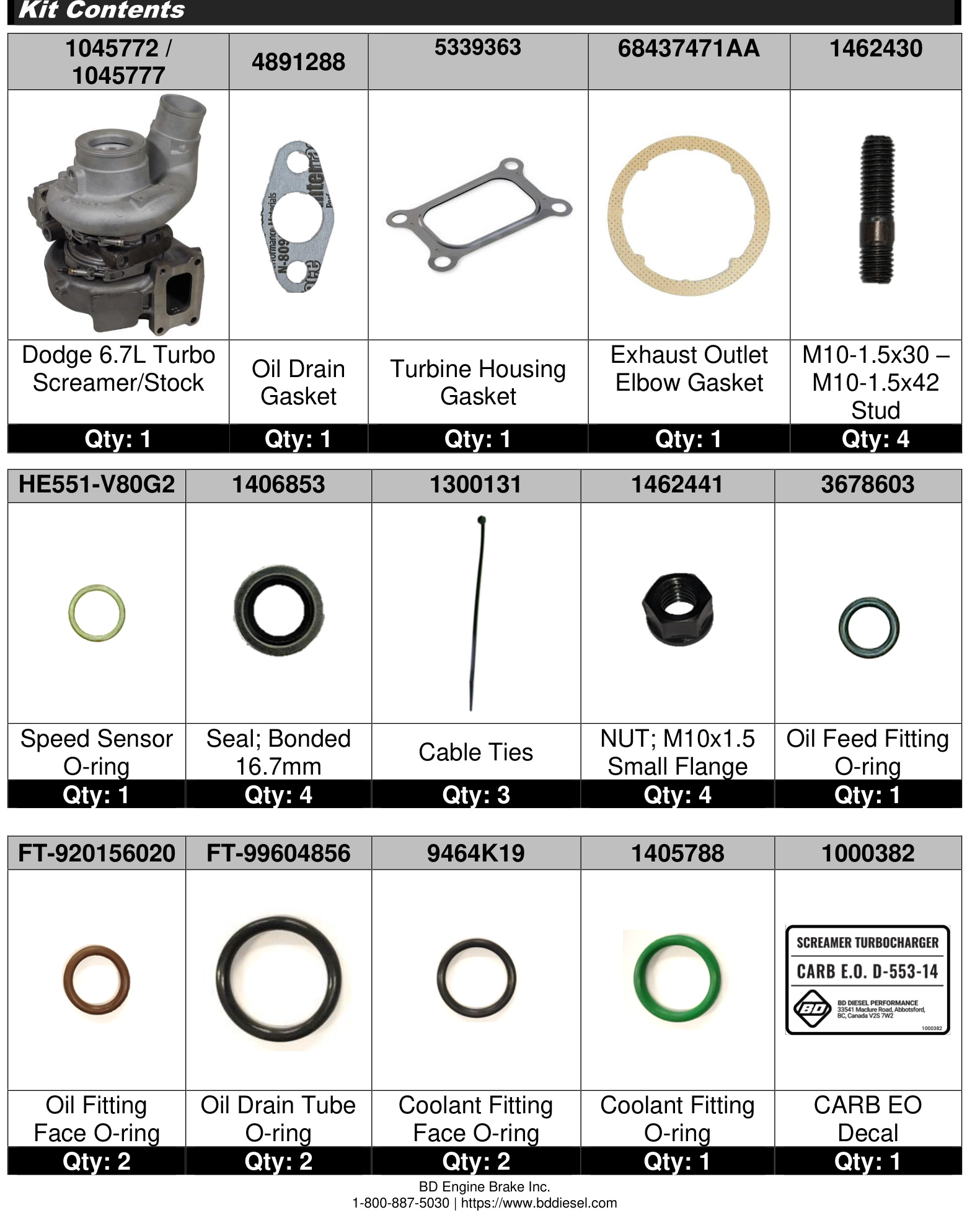
Kit Contents
- Dodge 6.7L Turbo, Screamer/Stock (P/N 1045772 / 1045777) — Qty 1
- Oil Drain Gasket (4891288) — Qty 1
- Turbine Housing Gasket (5339363) — Qty 1
- Exhaust Outlet Elbow Gasket (68437471AA) — Qty 1
- Stud, M10-1.5x30 – M10-1.5x42 (1462430) — Qty 4
- Speed Sensor O-ring (HE551-V80G2) — Qty 1
- Seal, Bonded 16.7mm (1406853) — Qty 4
- Cable Ties (1300131) — Qty 3
- Nut, M10x1.5 Small Flange (1462441) — Qty 4
- Oil Feed Fitting O-ring (3678603) — Qty 1
- Oil Fitting Face O-ring (FT-920156020) — Qty 2
- Oil Drain Tube O-ring (FT-99604856) — Qty 2
- Coolant Fitting Face O-ring (9464K19) — Qty 2
- Coolant Fitting O-ring (1405788) — Qty 1
- CARB EO Decal (1000382) — Qty 1
Removal
Disconnect the Batteries and Strip the Engine Bay
- Disconnect the Intelligent Battery Sensor (IBS) wire harness connector (1).
- Disconnect and isolate both of the negative battery cables (2).
IMPORTANT: The IBS must be disconnected before the battery cables to avoid damage!
- Remove the right-side inner fender.
- Drain the cooling system.
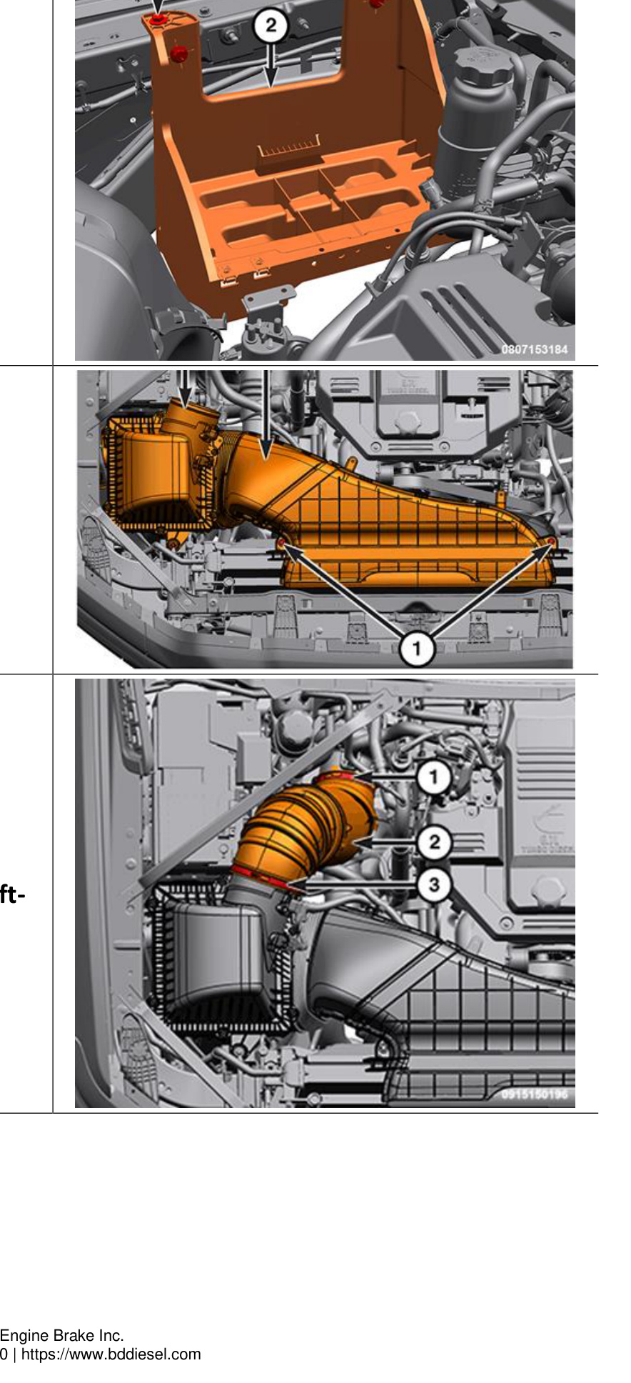
- Remove the radiator closure (2).
- Remove the air cleaner hose (2).
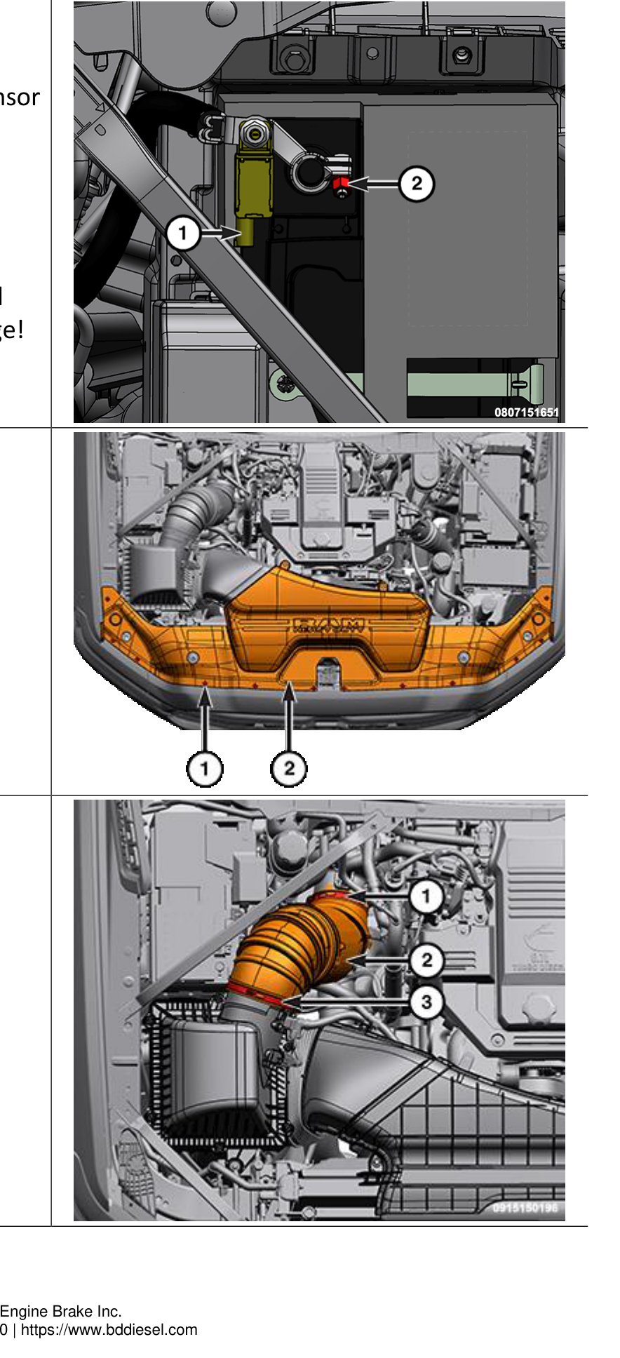
- Remove the entire air cleaner body.
- Remove the right battery tray (2).
- Remove the breather hose (2).

- Remove the right CAC tube (2).
- Remove the pressurized coolant bottle.
- Cut the cable ties (1, 2) securing the NOx sensor wire harness, actuator harness, and turbo speed sensor harness.
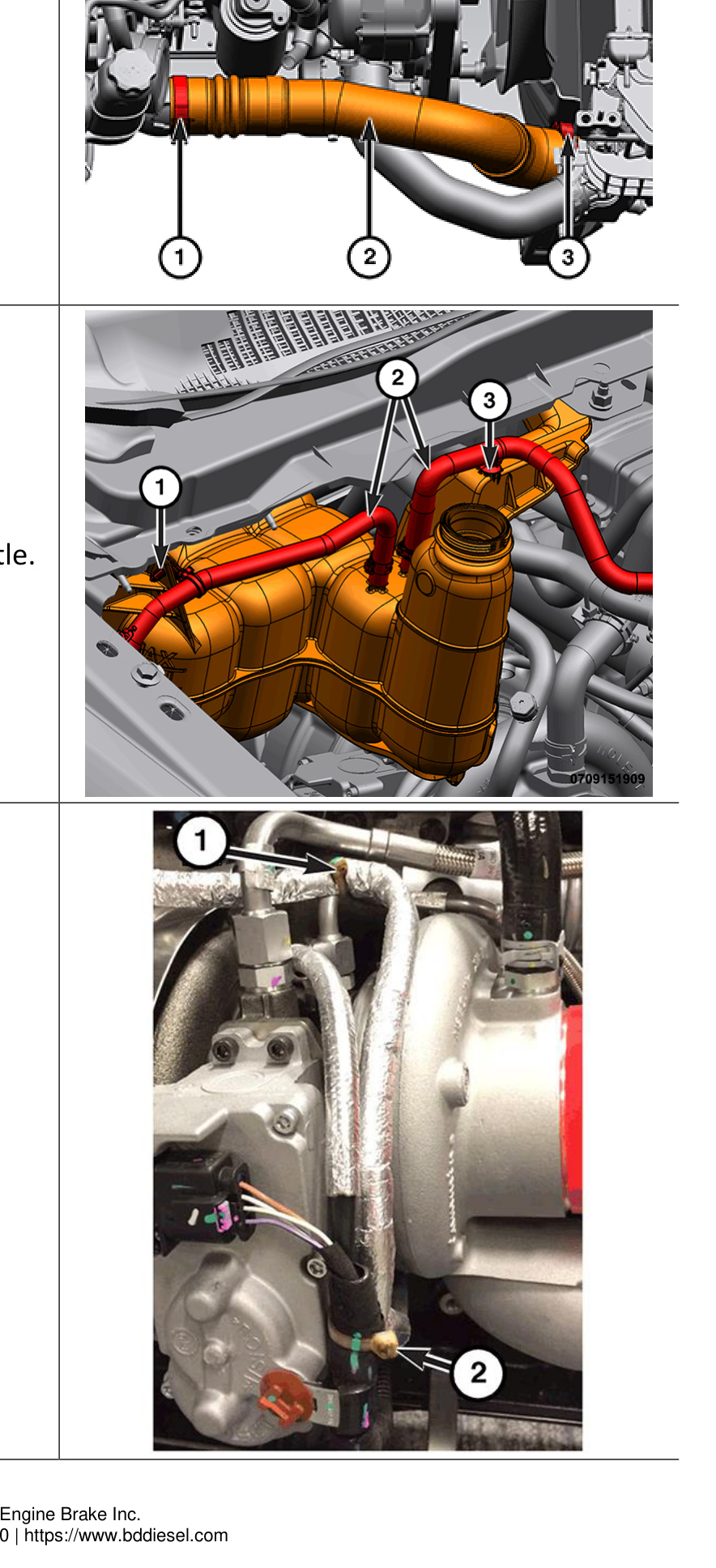
Disconnect the Turbo Harnesses
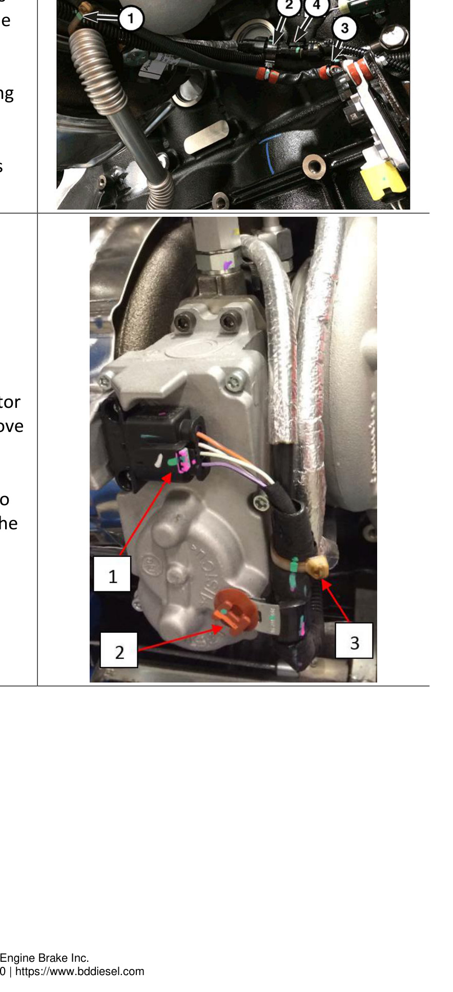
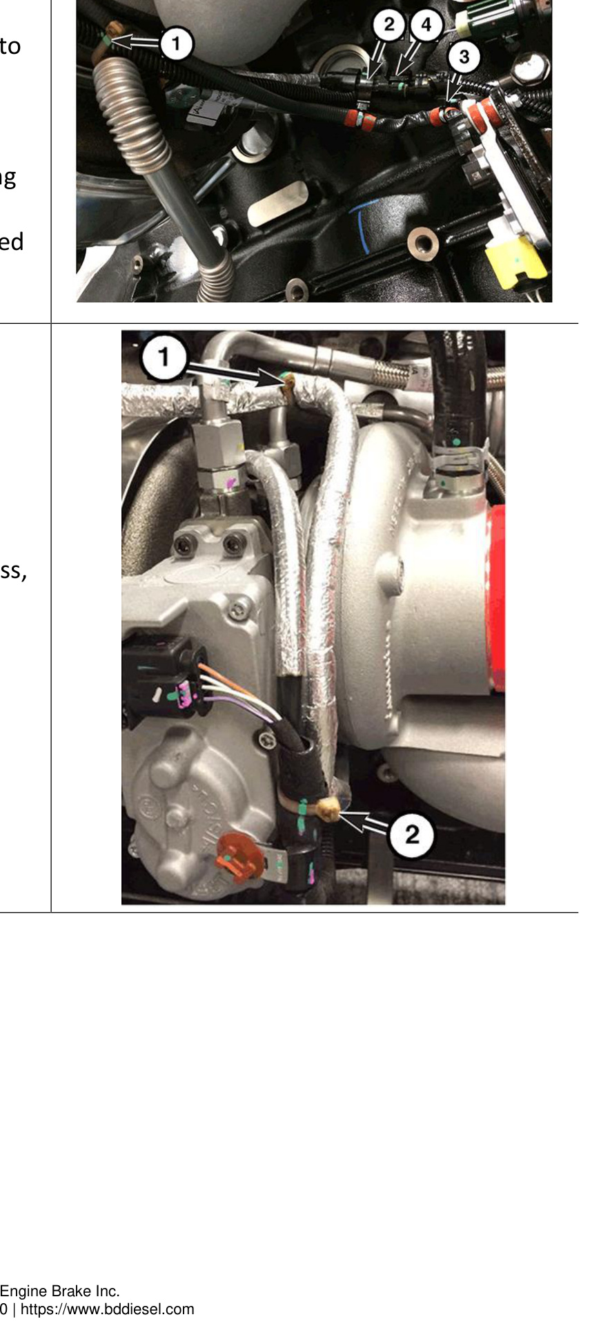
- Cut the cable tie (1) securing the NOx sensor harness, actuator wire harness and turbo speed sensor harness to the oil drain tube.
- Carefully separate the clip (2) securing the speed sensor harness connector.
- Disconnect the speed sensor harness connector (4).
- Unscrew the plastic clip (2) securing the harness to the actuator.
- Disconnect the actuator harness connector (1): clean the connector to remove debris, pull the light-gray release lever away from the locked position with your thumbnail until it clicks into the unlocked position, then hold the light-gray release lever down while pulling the connector apart.
Remove the Lines and Tubes
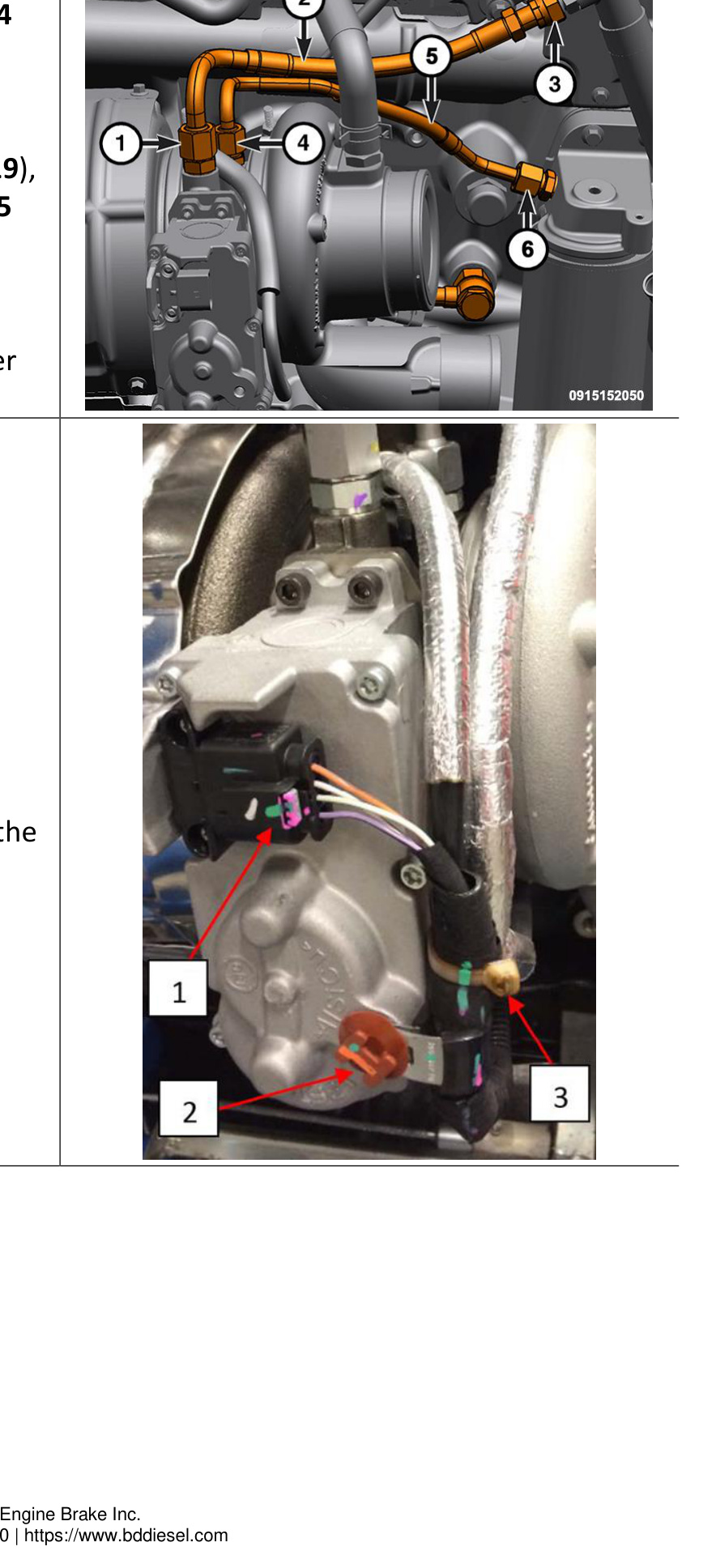
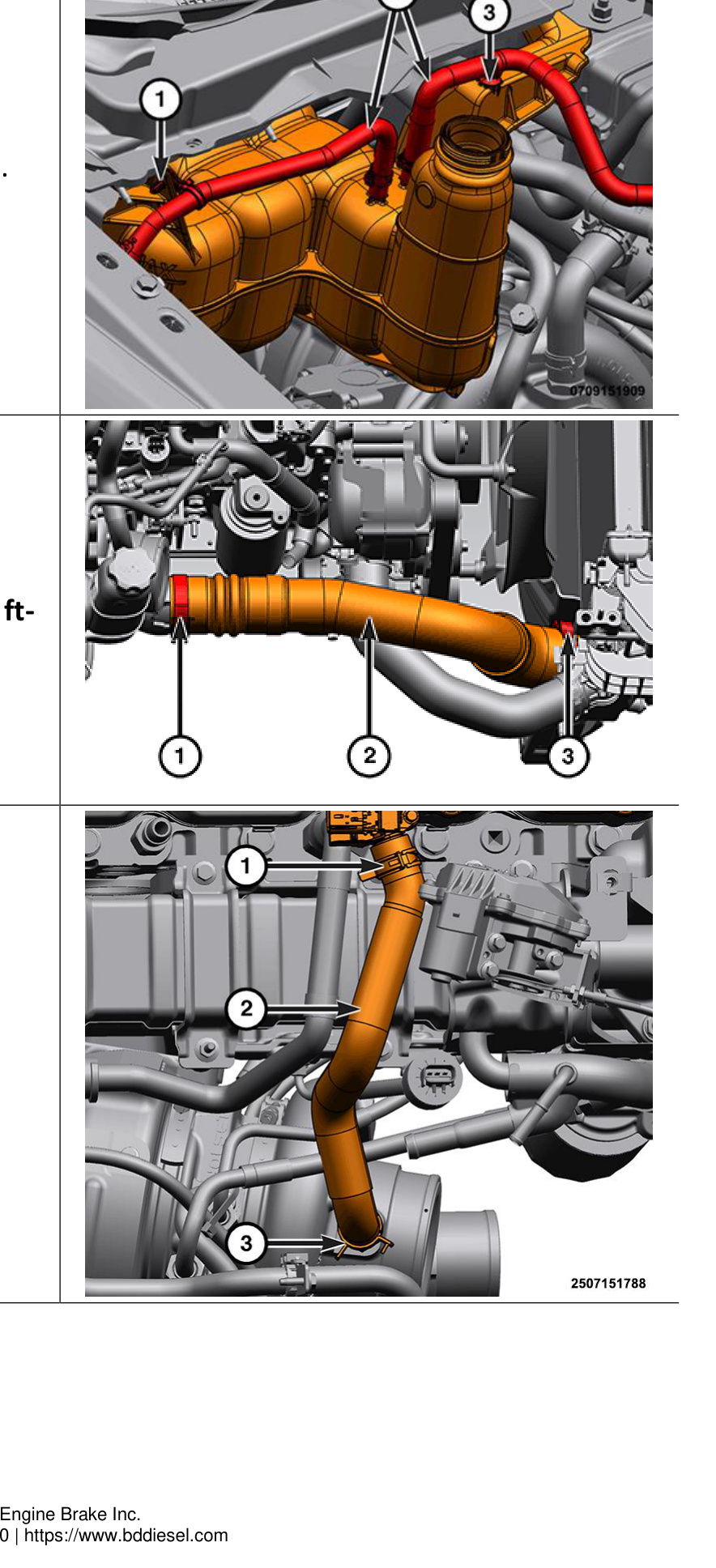
- Remove the union nuts (1, 3) and the coolant return line (2).
- Remove the union nuts (4, 6) and the oil supply line (5).
- Remove the bolts (1) and the oil drain tube (2) from the turbocharger.
- Remove the banjo bolts (3, 5) and the coolant supply tube (4).
- Remove the bolts (1, 3) securing the transmission oil cooler line bracket and the exhaust isolator (2) to the transmission.

Remove the Turbocharger
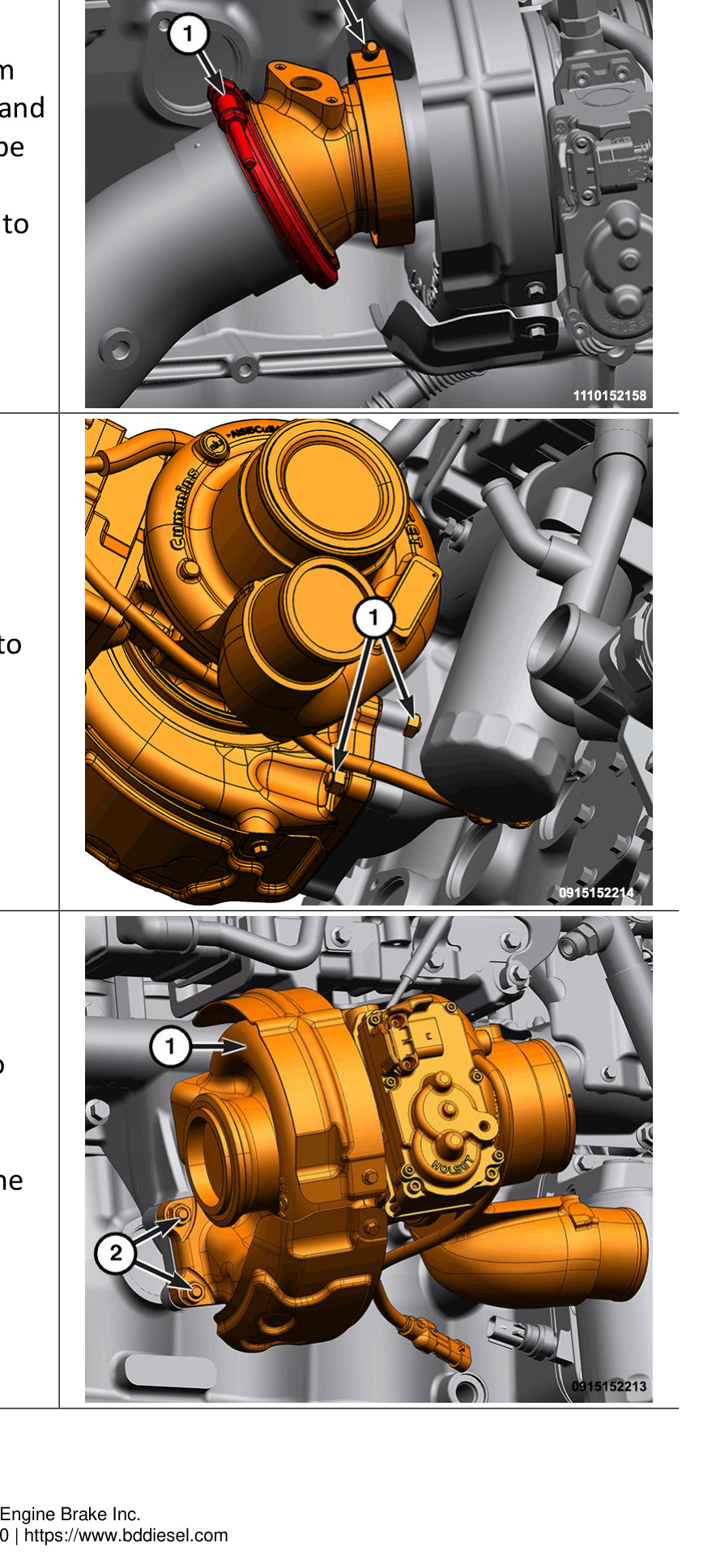
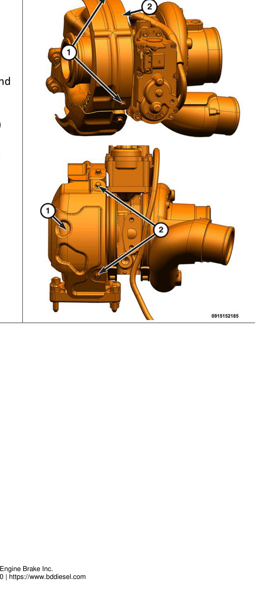
- Remove both band clamps (1, 2) from the exhaust outlet connector elbow, then reposition the elbow and the pipe out of the way. Note: The NOx sensor does not need to be removed for this step.
- Remove the right-side turbocharger-to-exhaust-manifold nuts (1).
- Remove the left-side turbocharger-to-exhaust-manifold nuts (2).
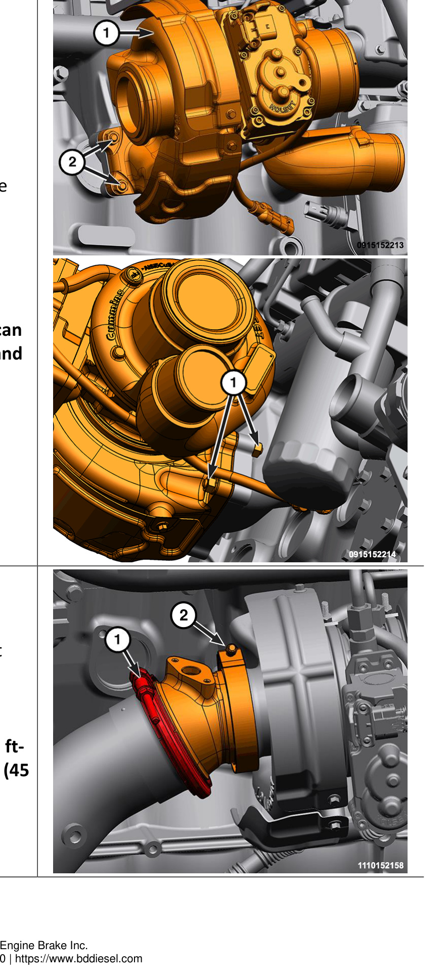
- Remove the turbocharger (1) from the vehicle through the right-side wheel well.
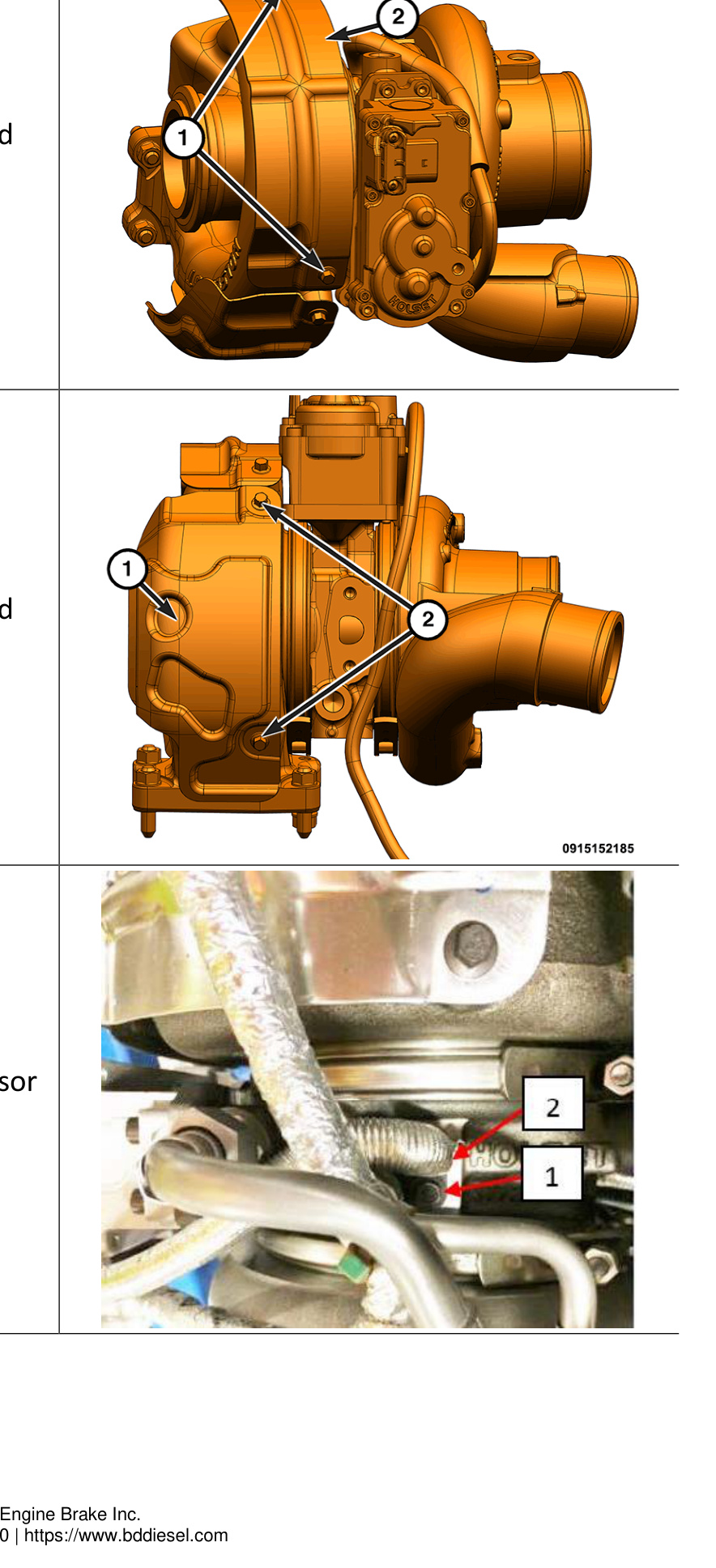
- If necessary, remove the bolts (1) and the upper heat shield (2).
- If necessary, remove the bolts (2) and the lower heat shield (1).
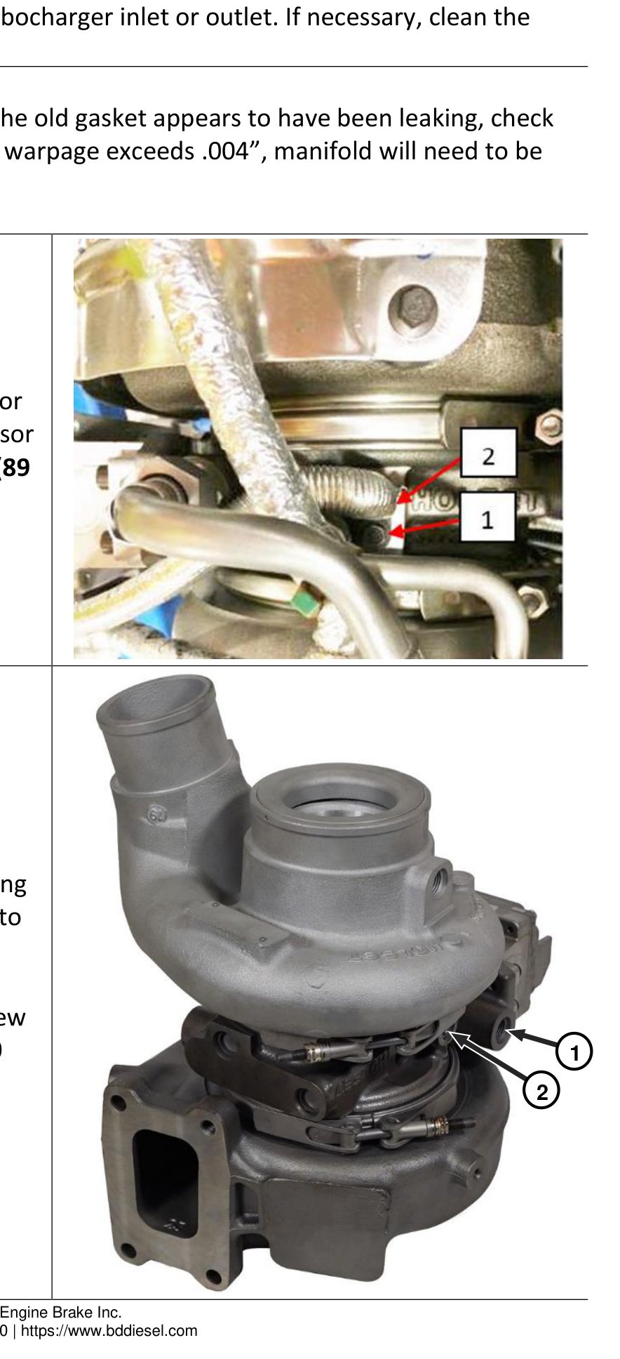
- Remove the turbocharger speed sensor (2), and set it aside to reuse later.
Installation
NOTE: Verify that the turbocharger and charge-air cooler are free of excess oil and debris. Do not allow any water or solvents to enter the turbocharger inlet or outlet. If necessary, clean the charge-air cooler.
Clean the turbocharger mating surfaces. If the old gasket appears to have been leaking, check the mounting flange with a straight edge. If warpage exceeds .004″, the manifold will need to be replaced or machined.
Prepare the New Turbocharger
- Replace and lubricate the speed sensor O-ring (HE551-V80G2). Install the sensor (2) and torque the bolt (1) to 10 Nm (89 in-lbs).
- Swap the coolant outlet fitting (1) using a new O-ring (1405788). Torque the fitting to 65 Nm (48 ft-lbs).
- Swap the oil inlet fitting (2) using a new O-ring (3678603). Torque the fitting to 30 Nm (22 ft-lbs).
- If removed, install the heat shields, and tighten the bolts to 11 Nm (8 ft-lbs).
- Install the three new studs (1462430) into the turbine inlet, and if desired, replace the single stud in the exhaust manifold flange.
- Pre-lube the turbocharger with 29.9–59.4 ml (1–2 oz) of clean engine oil.
Mount the Turbocharger
- Using a new gasket (5339363), install the turbocharger onto the exhaust manifold studs by coming through the wheel well, and tighten the new nuts (1462441) finger tight.
- Torque the nuts to 43 Nm (32 ft-lbs) using a cross pattern.
IMPORTANT: Improper flange torque can lead to an exhaust leak, gasket failure and flange damage.
- Using a NEW gasket (68437471AA) at the rear (1) of the exhaust outlet connector elbow, correctly align the elbow and pipe, then tighten the forward band clamp (2) to 17 Nm (13 ft-lbs) and the rear clamp (1) to 61 Nm (45 ft-lbs).
Reinstall the Lines and Tubes
- Install the exhaust isolator (2) and the transmission oil cooler line bracket to the transmission, and tighten the bolts (1, 3) to 24 Nm (18 ft-lbs).
- Replace the turbocharger drain tube O-rings (FT-99604856) (2).
- Lubricate the O-rings with clean engine oil, and install the turbocharger drain tube (1) into the engine block.
- Using a NEW gasket (4891288), install the turbo oil drain tube (2) and tighten the bolts (1) to 24 Nm (18 ft-lbs).
- Using NEW sealing washers (1406853), install the turbo coolant supply line (4) and tighten the banjo bolts (3, 5) to 35 Nm (26 ft-lbs).
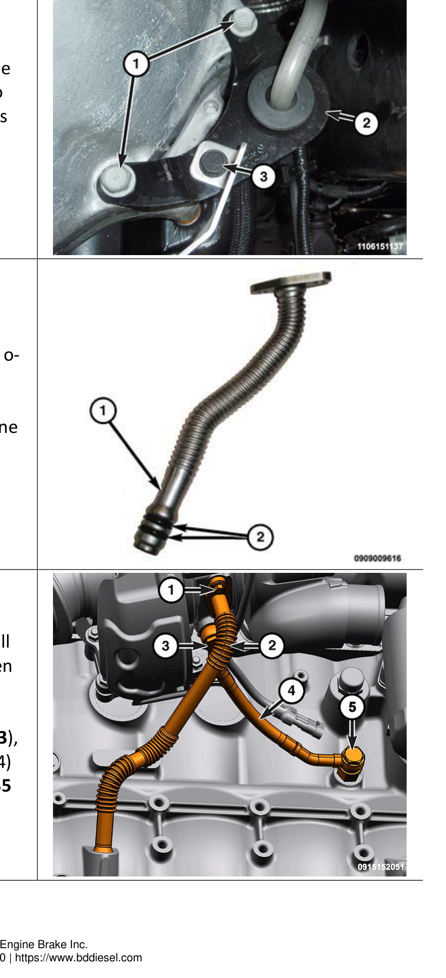
- Install the turbo oil supply line (5). Replace the face seal O-rings (FT-920156020) and tighten the union nuts (4, 6) to 24 Nm (18 ft-lbs).
- Install the coolant return line (2). Replace the face seal O-rings (9464K19) and tighten the union nuts (1, 3) to 35 Nm (26 ft-lbs).
NOTE: Ensure there is sufficient clearance between the lines and other components.
- Connect the turbo actuator harness connector (1).
- Screw in the plastic clip (2) securing the turbo actuator wire harness.
Reconnect the Harnesses
- Connect the turbo speed sensor harness connector (4).
- Attach the clip (2) in its original location to secure the turbo speed sensor connector.
- Install cable tie (1) (1300131) securing the NOx sensor wire harness, turbo actuator wire harness, and turbo speed sensor wire harness to the oil drain tube.
- Use a cable tie (2) to secure the NOx sensor harness, turbo actuator harness, and speed sensor harness.
- Use a cable tie (1) to secure the NOx sensor wire to the oil supply tube.
Reassemble the Engine Bay
- Install the pressurized coolant bottle.
- Install the right CAC tube (2), and tighten the clamp nuts (1, 3) to 11 Nm (8 ft-lbs).
- Install the breather hose (2).
- Install the right-side battery tray (2).
- Install the air cleaner body.
- Install the air cleaner hose (2), and tighten the hose clamps to 11 Nm (8 ft-lbs).
Final Assembly and Startup
- Install the radiator closure (2).
- Fill the cooling system.
- Install the right-side inner fender.
- Reconnect the batteries.
- Reconnect the Intelligent Battery Sensor (IBS) wire harness connector (1).
- Start the engine and check for any cooling or exhaust leaks, and confirm the turbocharger is operating properly.
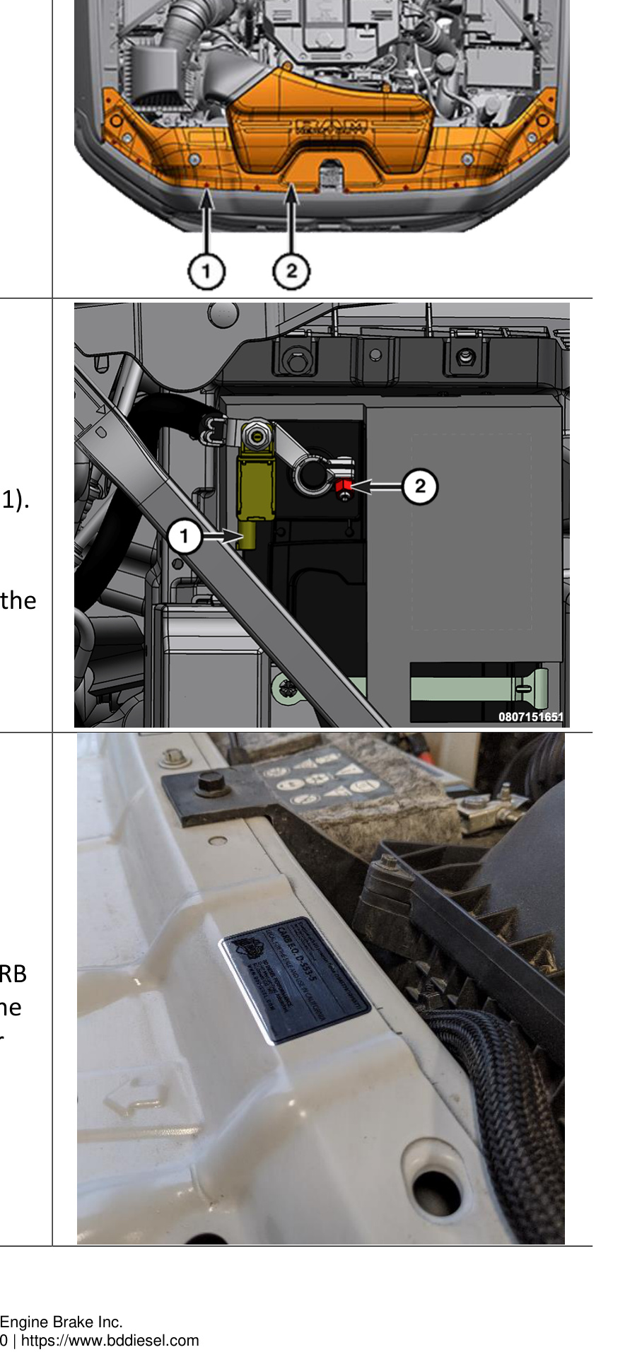
CARB EO Decal
For part number 1045772 only: If your vehicle is listed as covered under CARB EO D-553-14, apply the decal as shown to the vehicle — near the airbox. See the Applications section above for vehicle coverage.