
Installation instructions for the BD turbo-mount air exhaust brake, part #2023144, for 1999-2003 Ford 7.3L Powerstroke trucks. The exhaust brake adds controllable engine braking to reduce wear on your service brakes when towing or descending grades.
Download the Original PDF Manual
Thank you for purchasing a BD Engine Exhaust Brake. Before you begin, check that your kit contains all of the listed items and read this manual thoroughly. We strongly suggest writing down the part number and serial number for your records.
Brake Kit Contents
Kit #2023144 — Ford 7.3L Powerstroke Exhaust Brake:
- Valve Assembly
- DFIV Control Kit
- Vacuum Pump / Relay harness (1330440-C)
- Vacuum Pump relocation kit
- Air Pump Kit with bracket (1030125B)
- Air control kit (1220145-C)
- Retrofit Kit — California trucks only (1030125B-1)
- Air Pump Sub Assembly
Pre-Installation
IMPORTANT: To prevent damage to electronic components, disconnect both negative battery terminals before starting. Please read this manual thoroughly before installing this exhaust brake.
Special Tools Required
- Measuring tape or ruler
- Drill with 1/8″ and 3/16″ bits and a Unibit
- Sawzall or hacksaw
- Crimping pliers
- Test light
- 1/4″ drive socket set
- Small flat-blade screwdriver
- Welder
Optional Accessories
- Manual Transmission Shifter Switch Kit (1300210 / 1030900)
- BD X-Monitor Digital Gauge Kit (1087200)
- Performance Torque Convertor (1030223)
- Autoloc (1030390)
- BD Evolution Performance Tuner (1057100)
- Torqloc (1030395)
Notes on Connectors
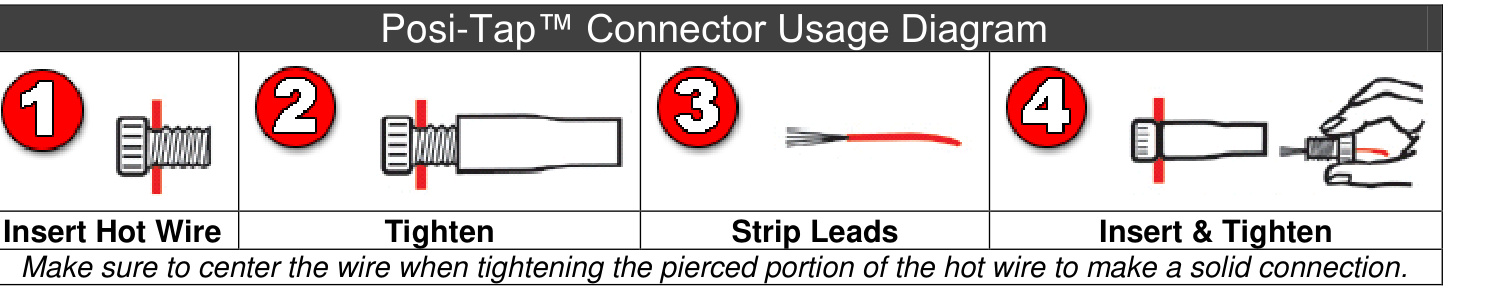
The kit includes a number of Posi-Tap™ connectors (Gray/Red, Black, or Green/Yellow) to tap onto OEM wiring. It is important to select the correct color of connector so it matches the gauge of the OEM wire it is being installed on. Using the incorrect connector could cause an inadequate connection and/or sever the OEM wire.
- 18–22 ga OEM wire → Gray or Red Posi-Tap™
- 12–18 ga OEM wire → Black Posi-Tap™
- 10–12 ga OEM wire → Green or Yellow Posi-Tap™
Though these connectors offer a quicker installation, the best option is to solder the wires and isolate the joints with heat shrink or liquid electrical tape. Proper soldering techniques should be used to ensure adequate connections.
WARNING: The ground terminals of the vehicle’s batteries must be disconnected before performing any piercing or Posi-Tapping onto any ECM/PCM wire.
Butt Connector with Heat-Shrink
- Insert the wires into the butt connector and crimp the connection.
- Heat the connection to shrink the casing and seal the joint.
Installation
Valve Installation
- Remove the engine-lifting eye by the turbo outlet. Remove and retain the turbo exhaust clamp between the turbo and exhaust pipe. Loosen the two bolts that secure the turbo down pipe to the catalytic convertor under the truck.
- Using a 5/16″ 12-point socket or wrench, remove the seven mounting bolts that secure the factory warm-up valve housing to the back of the turbocharger. You will reuse these same bolts to mount the BD brake assembly. Once loosened, turn the housing downward to expose the valve actuation rod.
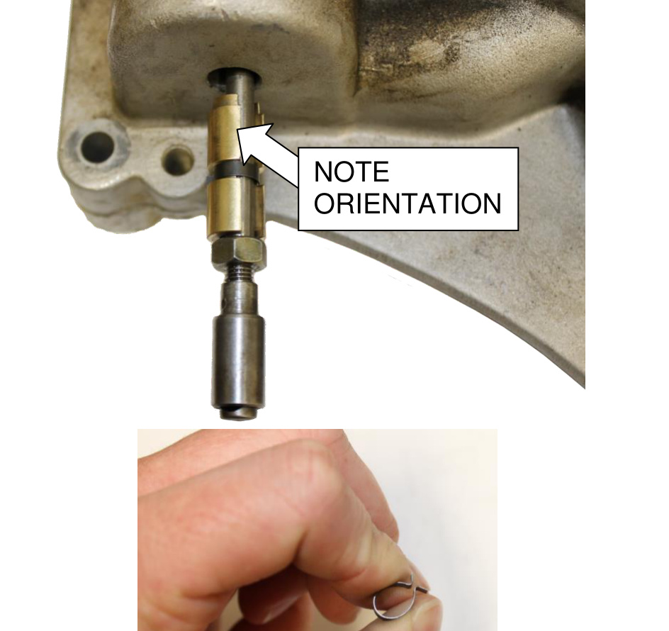
- Disconnect the actuation rod from the bottom of the outlet housing.
NOTE: The clip that holds the rod to the outlet housing is similar to that found on carburetors.
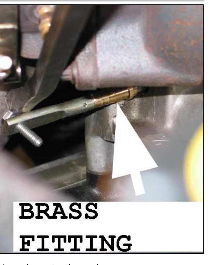
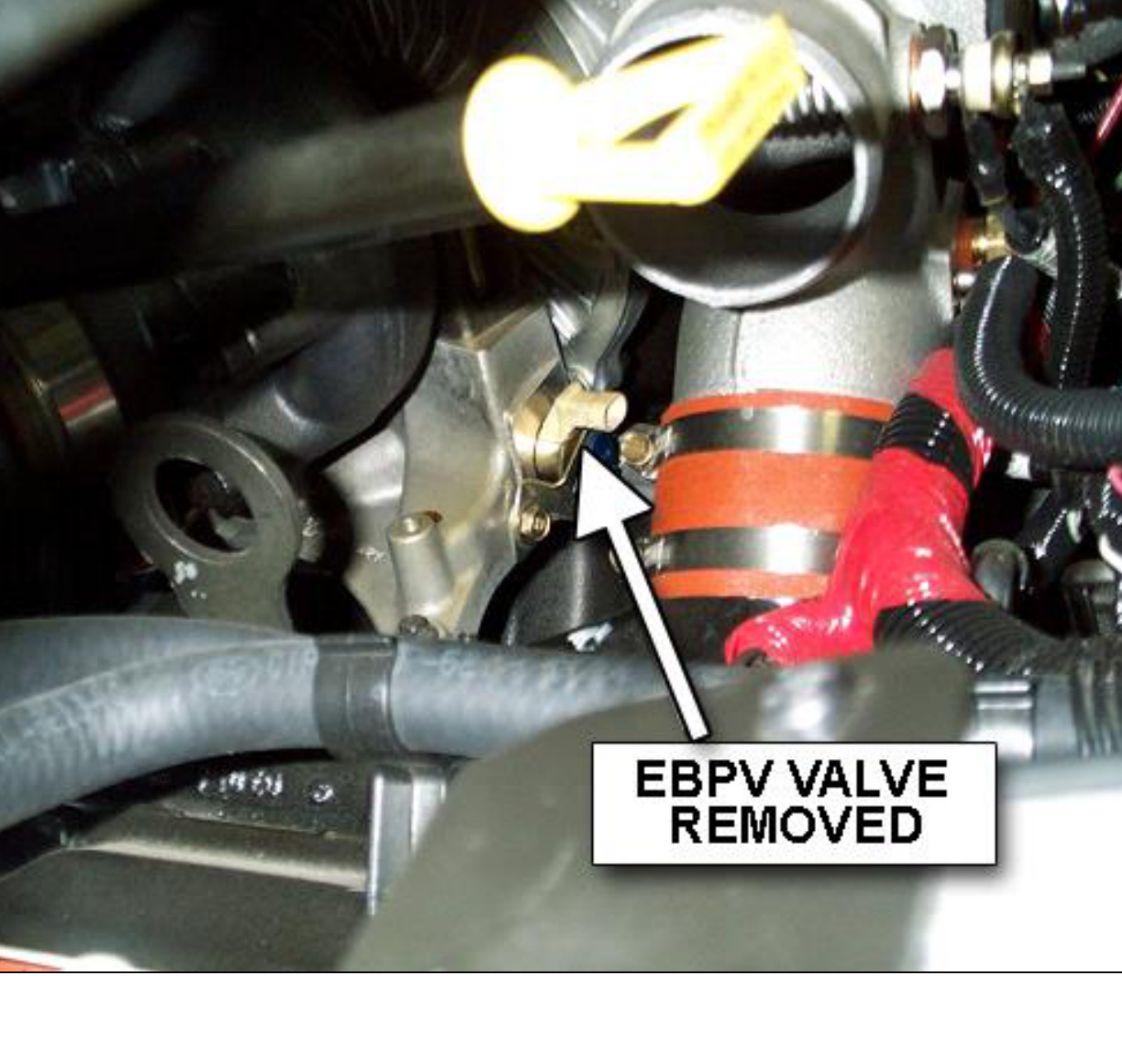
- To prevent the rod from hanging — which can cause the rod seal to leak due to vibration — install the supplied rod-support fitting. This brass fitting has a cut in it that fits around the rod and holds it securely. Give the clip a pinch before installing to ensure a strong fit.
The EBP valve will not be required with the BD exhaust brake installed. It is recommended that the EBP valve wiring harness be disconnected to prevent the actuator rod from moving and to protect the seal.
CALIFORNIA MODELS: On California model vehicles, the EBP valve wiring must be connected to ensure the ECM does not set an engine trouble code.
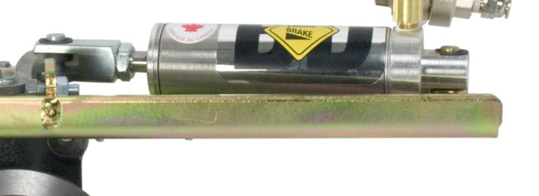
Install the BD brake valve assembly on the turbo using the original mounting bolts. Secure the exhaust pipe to the BD brake valve using the original turbo exhaust clamp, then reinstall the intercooler pipe and tighten the bolts on the catalytic convertor.
Stock Vacuum Pump & Reservoir Removal
- Locate the small electric vacuum pump and reservoir on the passenger-side fender well.
- Remove the reservoir by removing the bolts on the underside of the fender well, then disconnect the hoses.
- Remove the small electric vacuum pump by removing the screws, unplugging the electrical plug, and pulling off the supply tube to the reservoir.
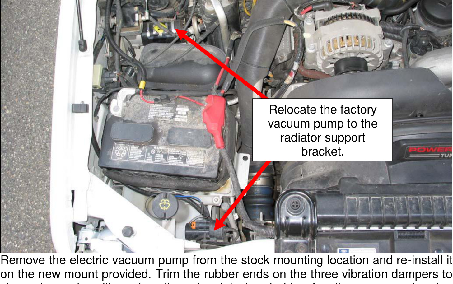
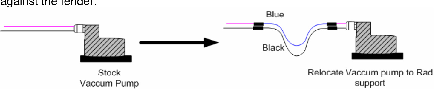
- Re-install the electric vacuum pump on the new mount provided. Trim the rubber ends on the three vibration dampers to clear when reinstalling. Install it on the right-hand side of the radiator support bracket with the two bolts and washers provided.
- Cut the power supply wires for the stock electric vacuum pump approximately 4″ from the connector and splice in the supplied black and blue wires using the butt connectors and shrink tubing. The 1/8″ plastic tube will run inside the same loom against the fender.
Regulator / Air Solenoid and Relay Installation
- Mount the regulator and air solenoid assembly above the air conditioning unit where the MAP sensor is located. Secure this and the relay assembly to one of the existing screws.
- Connect the relay harness: connect the ring terminal on the red wire (with built-in fuse holder) to the passenger-side positive battery terminal and the black ground wire to the negative terminal. Do not reinstall the battery yet.
- Connect the female 2-prong terminal to the male terminal on the air pump.
- Connect the male 2-prong terminal to the corresponding female terminal on the Regulator / Air Solenoid assembly.
- Route the plastic air hose from the 90° fitting on the compressor outlet over to the air solenoid assembly. Cut the hose to length and insert it into the fitting on the brass tee that also has the pressure switch threaded into it. Route the air-intake hose on the compressor to a clean, dry area in the engine bay and install the supplied “pancake” filter onto it.
- Route a section of the remaining 1/4″ plastic air line from the outlet fitting on the regulator to the inlet fitting on the quick-release valve on the side of the main air cylinder.
DFIV Installation
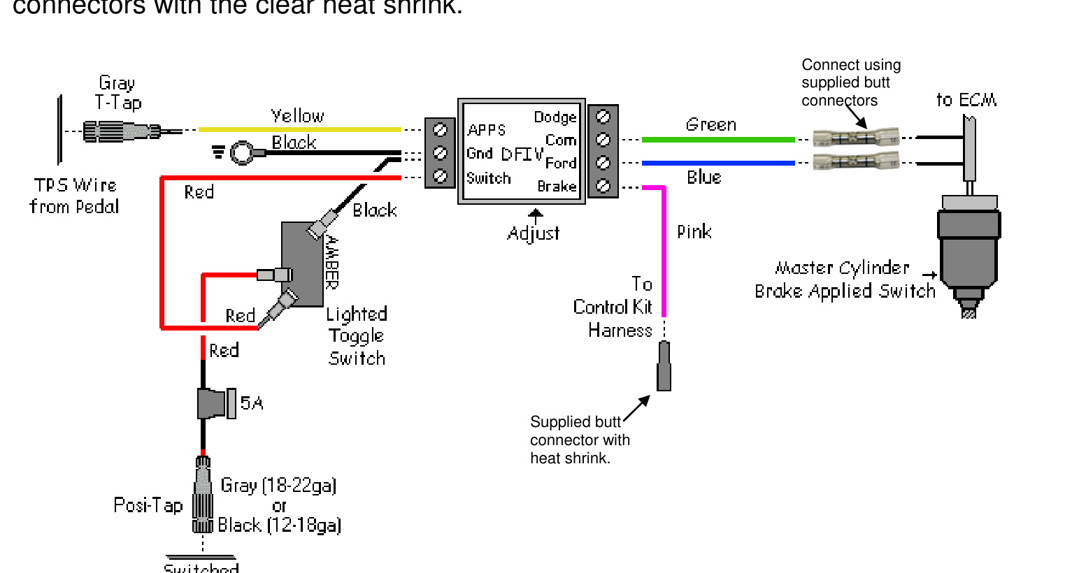
- Route the Green, Blue and Pink wires from the DFIV through the firewall. (If the vehicle does not have cruise control, you can remove the Green and Blue wires from the DFIV and discard them.) Connect the Pink wire to the corresponding Pink wire on the Air Solenoid and Regulator assembly using one of the provided crimp connectors with clear heat shrink.
- Remove the lower section of dash, under the steering column, and mount the DFIV module to the cross member under the steering column. Connect the Black wire from the DFIV module to a good ground.
- Locate the Throttle Position Sensor at the throttle pedal and, using a red Posi-Tap connector, attach the Yellow wire from the DFIV module to the Grey wire with White tracer on the TPS.
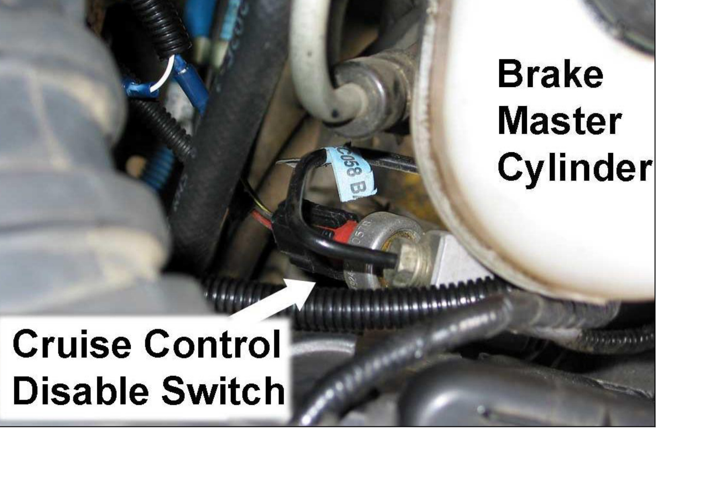
- Locate the Black with Yellow tracer wire at the Cruise Control Disable (Brake Applied) switch on the brake master cylinder and expose the wiring approximately 4 to 6 inches from the switch.
NOTE: This wire may be a different color in various applications. If there is no Black with Yellow wire going to this switch, use a test light to check which wire changes state (power to no power) when the brake pedal is applied.
- Cut the black wire with yellow tracer (BK/Y) and attach the blue Posi-Lock connectors to both sides of the cut wire.
- Run the supplied green and blue wires (brought through the firewall) to the Brake Applied switch at the brake booster and trim to fit. Connect the blue and green wires to the Posi-Lock connectors installed earlier on the black/yellow wires. It does not matter which wire connects where.
Switch Install (Dash-Mounted Toggle Switch)
If you wish to use the optional shifter-mounted switch instead, you can skip this section and go to the Manual Shifter Switch instructions below.
- Choose a spot on the dash to mount the toggle switch, ensuring there is room behind for the switch body. Drill a 1/8″ pilot hole, then enlarge it with a Unibit to 1/2″ and mount the toggle switch.
- Locate one of the ignition-switched Red/Black tracer wires under the steering column (one is 10/12 ga and the other is 14/16 ga) and connect an appropriate Posi-Tap (yellow for 10/12 ga, black for 14/16 ga, red for 18/20 ga).
- Connect the toggle switch’s red wire (with built-in fuse holder) to this Posi-Tap. Connect the other red wire from the toggle switch to the “Switch” terminal on the DFIV. Connect the black ground wire on the toggle switch to the “Gnd” connection on the DFIV.
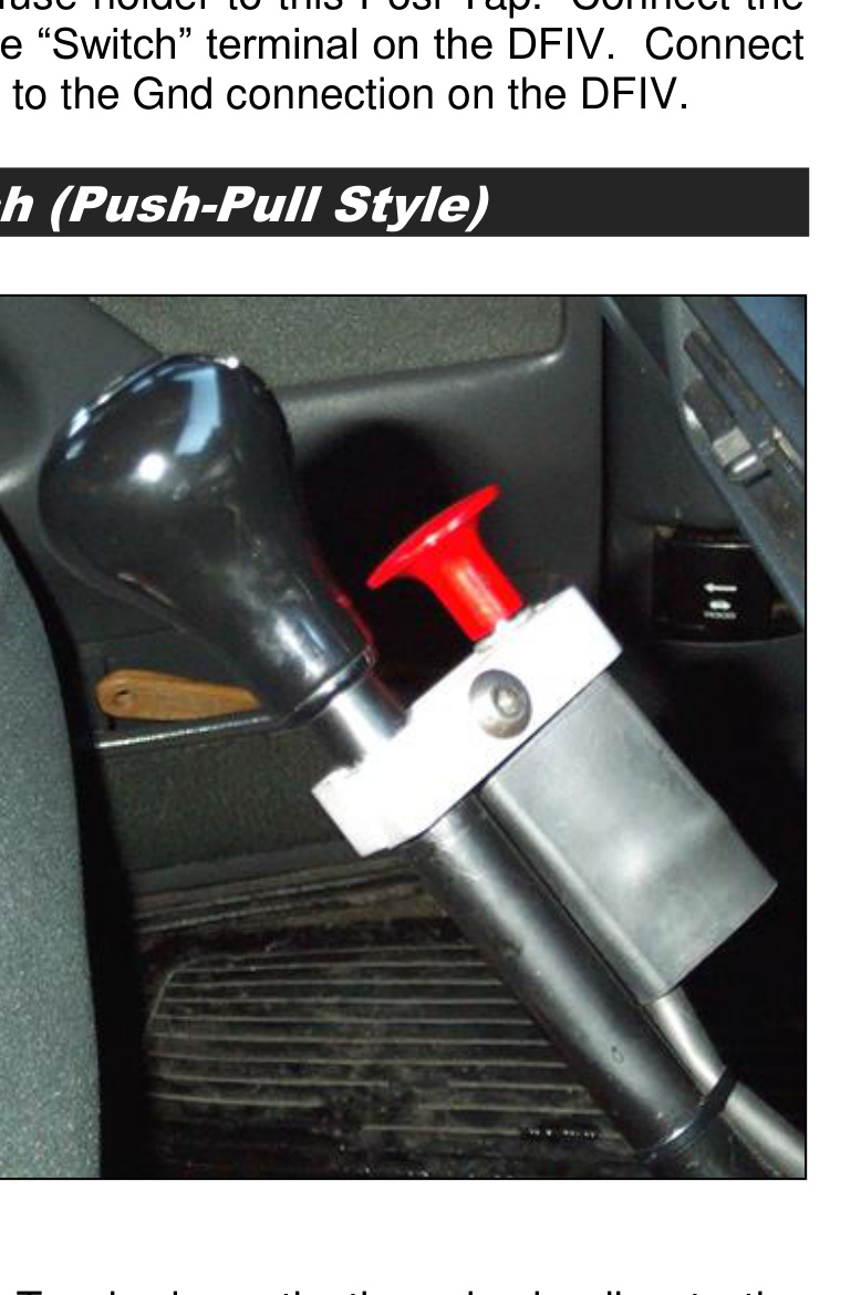
Optional Manual Shifter Switch (Push-Pull Style)
- Mount the shifter switch onto the shift lever using the supplied clamp (either 5/8″ or 3/4″).
- Run the electrical cable down the shifter shaft, securing it with zip-ties or electrical tape, and run it under the carpet to the firewall and under the dash. Leave enough slack for proper shifting of the transmission lever and to prevent any rubbing of wire.
- At the end of the cable, cut off any excess and strip away about 1 to 2 inches of the black rubber covering to expose the black and white (or green) wires, then strip the insulation from the ends of the two wires.
- Connect the white (or green) wire to the Tan brake activation wire leading to the ECM. Connect the black wire to a nearby ground source.
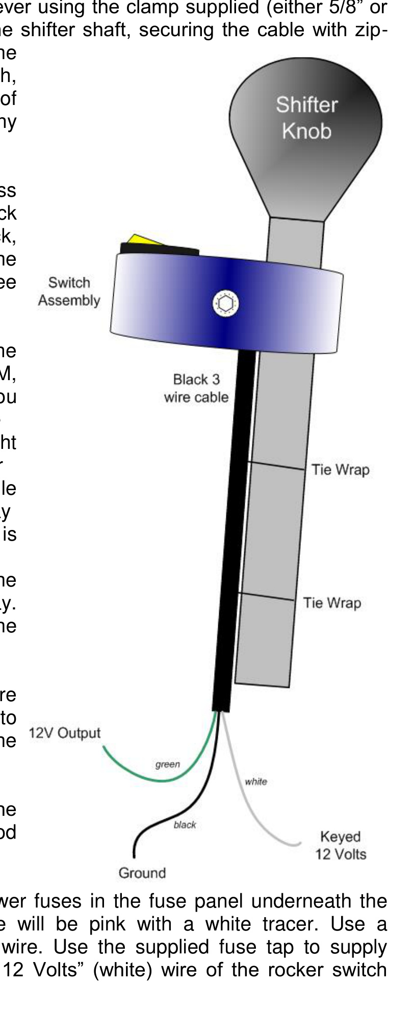
Optional Manual Shifter Switch (Rocker Switch Style)
- Mount the shifter switch onto the shift lever using the supplied clamp (either 5/8″ or 3/4″). Run the electrical cable down the shifter shaft, securing it with zip-ties or electrical tape, and run it under the carpet to the firewall and under the dash, leaving enough slack for proper shifting.
- At the end of the cable, cut off any excess and strip away about 1–2″ of the black rubber insulation to expose the black, white and green wires, then strip the insulation from the ends of the three wires.
- Because the exhaust brake controls run through the ECM, a relay kit must be installed (unless you are installing the push-pull switch for manual transmissions). This lets the light on the rocker switch illuminate while the exhaust brake is engaged. The relay comes pre-wired and is included in the main toggle switch kit.
- Connect the Tan wire coming from the ECM to terminal #87 on the relay. Connect the green 12V output wire to #85 on the relay, which then leads to the Tan brake activation wire going to the ECM.
- Attach the 5/16″ ring connector on the black ground wire to a good ground nearby.
- Locate one of the ignition-switched power fuses in the fuse panel under the steering column (traditionally pink with a white tracer). Use a voltmeter to confirm the wire, then use the supplied fuse tap to supply ignition-switched power to the “Keyed 12 Volts” (white) wire of the rocker switch assembly.
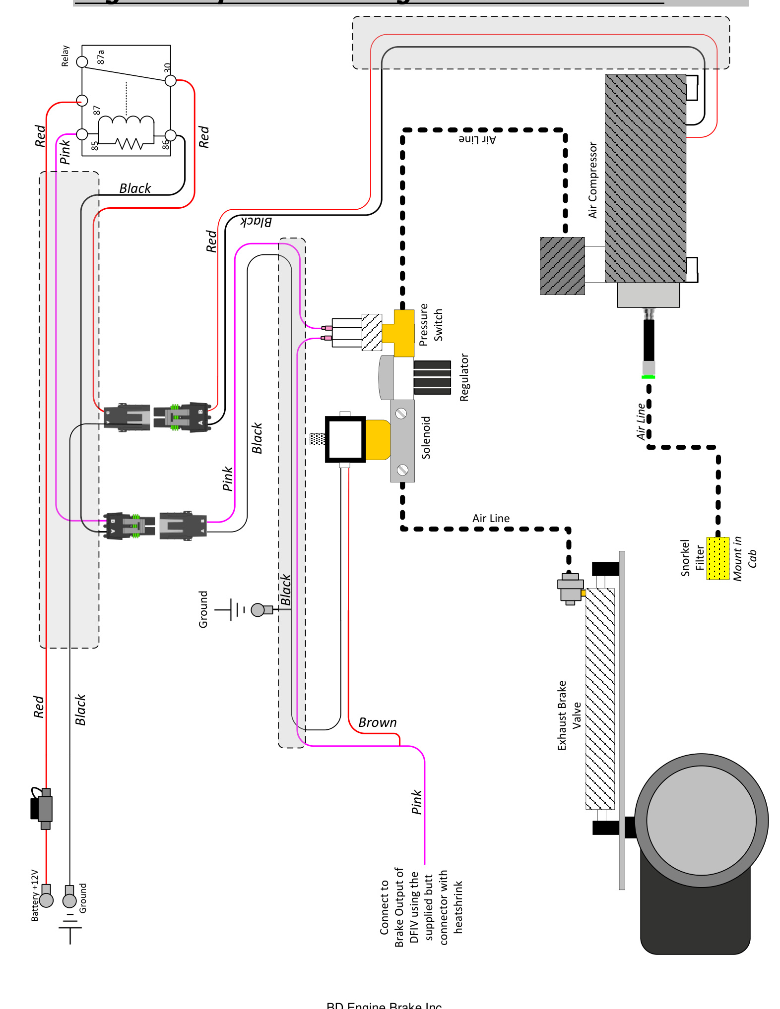
Engine Compartment Wiring & Hose Connections
Use the diagram below to verify all wiring and air-hose routing between the battery, relay, regulator, air solenoid, pressure switch, air compressor and the exhaust brake valve. The brake valve air line connects to the brake output of the DFIV using the supplied butt connector with heat shrink.
DFIV Calibration
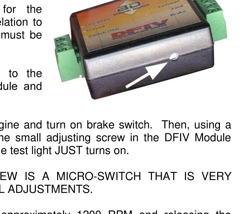
Ensure the connections of the corresponding wires to the DFIV control module are correct as shown in the wiring diagram. To achieve the correct activation point of the exhaust brake relative to the throttle pedal, the DFIV module must be calibrated for your vehicle.
- Connect one end of a test light to the “BRAKE” terminal of the DFIV module and the other end to a good ground.
- With the throttle at idle, start the engine and turn on the brake switch. Using a small flat-blade screwdriver, turn the small adjusting screw on the DFIV module counterclockwise or clockwise until the test light just turns on.
CAUTION: The adjusting screw is a micro-switch that is very delicate, so turn it using small adjustments.
- Test by revving the engine to approximately 1200 RPM and releasing the throttle. As the accelerator pedal is applied, the test light should turn off just before the engine starts to rev, indicating proper calibration with the APPS.
- The test light should activate again when the throttle pedal is returned to idle. If not, readjust the DFIV module so that it does. Reinstall the lower dash cover.
Battery & Intercooler Pipe Removal
For access to the EBP valve and turbo outlet earlier in the install, you will need to remove the passenger-side battery and the intercooler pipe.
- Disconnect the negative terminals on both batteries, then disconnect the positive terminals. Remove the passenger-side battery.
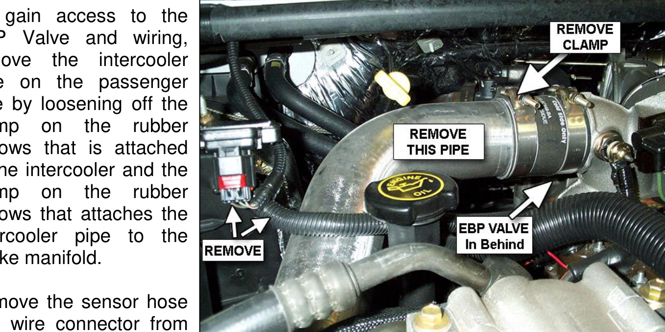
- To gain access to the EBP valve and wiring, remove the intercooler pipe on the passenger side by loosening the clamp on the rubber bellows attached to the intercooler and the clamp on the rubber bellows that attaches the intercooler pipe to the intake manifold.
- Remove the sensor hose and wire connector from the MAP sensor.
- When removing the pipe, the lower rubber bellows that connects to the intercooler should remain on the pipe. The pipe slides out of the rubber bellows that is still attached to the intake manifold.
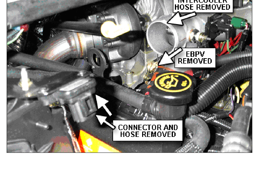
- Remove the turbo outlet housing. Inspect the turbo exhaust clamp, turbo down pipe and turbo outlet for any carbon build-up or damage that may cause problems sealing on exhaust mating surfaces.
Air Compressor
- Install the mounting bracket of the BD air compressor in the same location the small electric vacuum pump was removed from. Secure it to the side of the engine compartment with the supplied fender screws.
- Install the BD air compressor onto the bracket with the washers and lock nuts supplied, and re-install the vacuum reservoir in its original location. Re-attach all hoses that were previously disconnected.
Ford Exhaust Brake Retrofit Kit (California Trucks)
The purpose of this kit is to cure the problematic Ford P-Code regarding exhaust back pressure being too high. This code is normally set on California Powerstrokes when using an exhaust brake. This kit should only be used on California trucks that exhibit the problem.
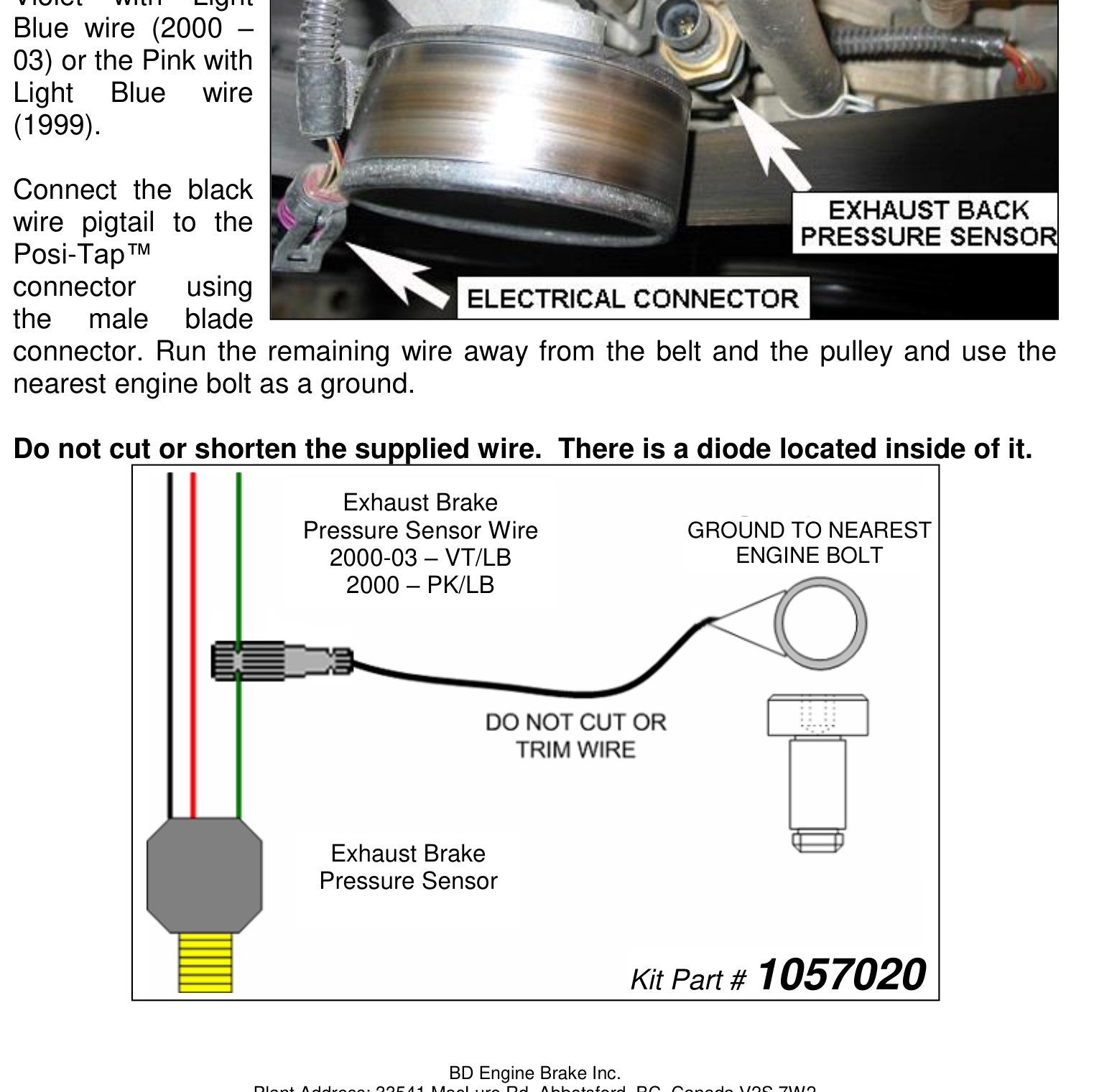
- Locate the Exhaust Back Pressure sensor at the front of the engine, just behind the idler pulley and to the left of the water pump outlet hose.
- Install the supplied Posi-Tap™ connector onto the Violet with Light Blue wire (2000–03) or the Pink with Light Blue wire (1999).
- Connect the black wire pigtail to the Posi-Tap™ connector using the male blade connector. Run the remaining wire away from the belt and pulley and use the nearest engine bolt as a ground.
IMPORTANT: Do not cut or shorten the supplied wire — there is a diode located inside of it. (Exhaust Brake Pressure Sensor Kit, Part #1057020.)
Battery Reinstall
Reinstall the passenger-side battery. Reconnect the positive terminals on both batteries, then reconnect the negative terminals.
Maintenance
- To extend the life of the exhaust brake, do not operate the vehicle for extended periods without activating the brake.
- On a twice-yearly interval, check and adjust the brake pressure to 10–15 lbs while the engine is at idle.
- Inspect the hoses, wires, fittings and clamps on a regular basis for any deterioration, damage or leaks.
- Trace hoses and wiring, check continuity through electric components, and check for any disconnected lines using the diagrams in this manual.
- To prevent the butterfly from sticking due to carbon build-up, daily use is recommended — simply switching the brake on and off a couple of times a day will help.
Operating Guidelines
An exhaust brake increases the driveline drag of your vehicle without using the hydraulic brakes. With loads being towed, the extra retarding force when slowing down or maintaining speed on downward grades reduces strain on the hydraulic braking system — reducing heat build-up, fade and wear on linings and drums.
- The exhaust brake helps maintain a controlled speed on a downward grade and slows the vehicle for turns or exit ramps without using the hydraulic brakes.
- It cannot be used as a parking brake or service brake to bring the vehicle to a complete stop, and is not a substitute for your hydraulic brakes.
- When the toggle switch is “On,” the valve activates every time you take your foot off the throttle pedal. Applying the throttle again opens the valve.
- Exhaust brakes are designed to operate with the throttle at idle, not in conjunction with cruise control, and not to aid in gear shifting. Vehicles may require downshifting to obtain the necessary retarding force.
- Automatic transmissions with lock-up converter clutches achieve the best retarding force with a clutch control device (e.g. AutoLoc).
- During cold-weather start-up, turn the brake on at idle while warming up the vehicle to reach operating temperature faster.
- For best results on a downhill grade, select a gear that lets you maintain a constant speed with little or no use of the hydraulic brakes — typically the same gear you would use to climb the grade.
NOTE: The brake pressure at idle should be checked and adjusted at the time of installation, two weeks after installation, and on a regular twice-yearly interval. Using a standard pressure gauge at the pressure port on the exhaust valve, set the idle brake pressure between 10 and 12 lbs.
Exhaust Back Pressure Testing (Air-Actuated Brakes)
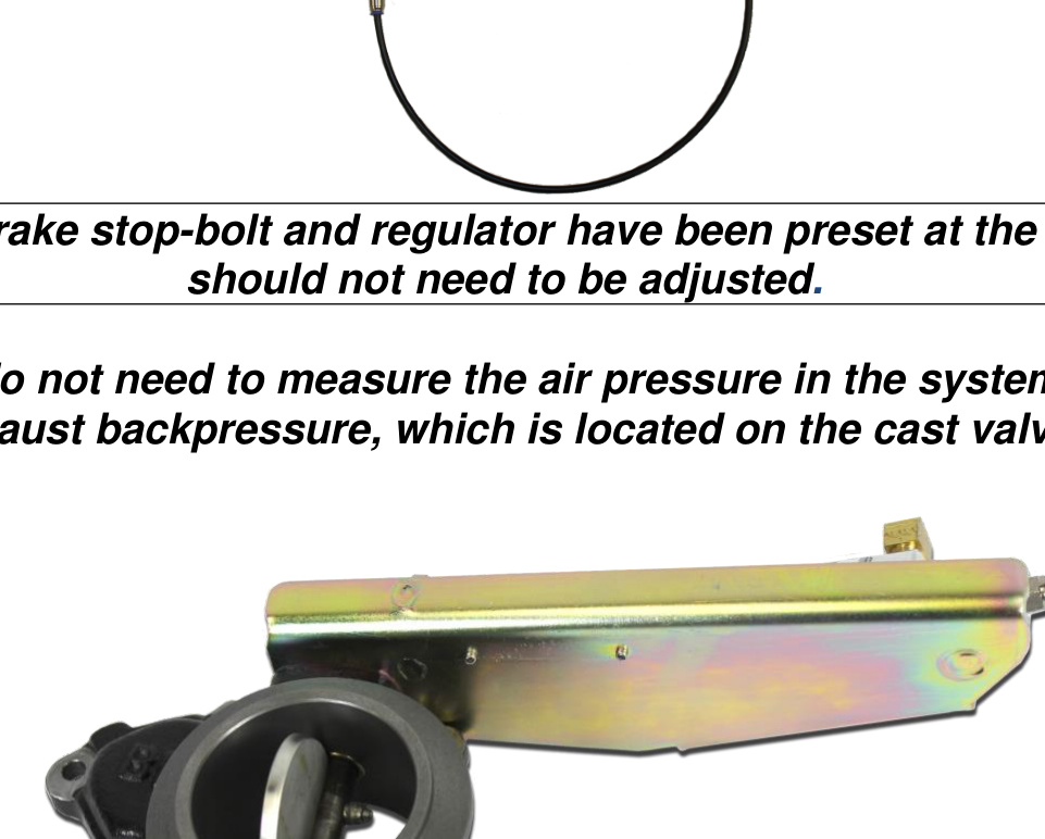
We recommend purchasing the BD pressure gauge kit (#1030050) for these tests. You do not need to measure the air pressure in the system — just the exhaust backpressure, which is measured at the cast valve.
NOTE: The brake stop-bolt and regulator have been preset at the factory and should not need to be adjusted.
Idle Pressure Test
With the BD brake engaged and the engine at idle, check the exhaust backpressure using a pressure gauge at the test port on the brake valve.
- Below 13 psi at idle: The most common cause is an exhaust leak at the clamp joint or at the welds. Apply the exhaust brake and have someone help you look for soot trails or a visible leak. Other culprits include an exhaust manifold leak, turbocharger gasket leak, turbocharger problem or an EGR issue.
- Greater than 25 psi: Make an adjustment on the stop bolt. Loosen the jam nut and lengthen the stop bolt toward the actuator (this shortens the stroke distance). Turn only 1/4 rotation at a time, re-secure the jam nut, and retest idle pressure.
NOTE: We generally do not recommend adjusting the stop bolt — please consult BD before doing so, as it may void your warranty.
Off-Idle Pressure Test & Adjustment
Your BD exhaust brake is a variable-orifice design, so when the brake is active and the engine is at higher RPM the brake lever does not rest on the stop bolt. Off-idle backpressure is set by adjusting the air pressure regulator. Secure your pressure gauge where you can see it while driving — a long extension hose bringing the gauge into the cab through an open window, or clipped under a windshield wiper, works well.
- Get the truck up to speed (a downhill grade or a load helps) and activate the exhaust brake. Note the maximum backpressure achieved — you should get peak backpressure at higher RPM (try 3000 RPM in Drive).
- If you cannot reach the desired backpressure, first look for exhaust leaks at the clamps, exhaust manifolds, feed pipes, the back of the turbo and the down pipe. A small leak can significantly decrease backpressure.
- If all connections are sealed, use the adjusting regulator to set the backpressure. Turning the regulator clockwise increases pressure; counterclockwise decreases pressure. Small adjustments have a significant effect.
NOTE: Over the first two weeks, the backpressure at idle may rise due to initial carbon build-up inside the brake housing and on the butterfly. The stop bolt may need to be readjusted to compensate.
Maximum Back Pressure by Application
- GM / Chevy 6.5 — 35 psi
- GM / Chevy Duramax — 55 psi
- Ford Powerstroke — 45 psi
- Dodge Cummins 1988–98 12V without 60 lb springs — 40 psi
- Dodge Cummins 1988–98 12V with 60 lb springs — 60 psi
- Dodge Cummins 2002 and newer — 60 psi
HD spring part #1030060.
CAUTION: Do NOT exceed the maximum back pressure value for the exhaust system. Exceeding this pressure will force the exhaust valves open during the intake stroke, which could cause engine damage.
Air Brake Troubleshooting Guide
This guide assumes your exhaust brake system uses a DFIV and a BD air compressor. If your system uses a microswitch for throttle activation, the air solenoid and pump operate the same as with the DFIV. If you are using existing on-board air, check that system as appropriate.
When I let off the throttle, nothing happens
- Confirm the DFIV is powering its “brake” output when the throttle is at idle and the brake switch and ignition are both on. If not, check that the DFIV has good power, ground and throttle signal, and check the DFIV adjustment. If these check out but the DFIV still won’t power the “brake” output, the DFIV is likely faulty.
- Check power and ground at the pump relay and make sure the air solenoid has a good ground. Verify that when the air solenoid is powered, it allows air to flow from the #2 port out the #1 port.
- Check that the pump relay is powering the pump. If the pump has power but does not run, the pump is likely faulty. If power and ground at the relay are good but the relay does not click or power the pump, the relay is likely faulty.
The brake comes on but there’s little or no holdback
- Check that the torque converter stays locked up during deceleration. If it unlocks, engine RPM falls to idle when the throttle is released, and the brake will be ineffective.
- Check off-idle brake pressure against the back pressure chart above. If you are not getting maximum allowable backpressure, check for exhaust leaks (a small leak can significantly decrease backpressure) and air leaks in the brake system. If none are found, try adjusting the air regulator.
- Try downshifting more aggressively — more RPM gives more holdback. If the problem persists, the transmission or torque converter could be slipping internally.
Everything seems to work, but the brake valve won’t close
- Check that air is reaching the brake air cylinder. If not, the air solenoid or quick-release valve is likely stuck, plugged or faulty — clean or replace as required.
- If air is reaching the cylinder, the cylinder or brake valve may be seized. Remove the clevis pin on the end of the cylinder rod and see if the valve lever can be moved freely.
- If the valve lever moves freely, the cylinder is stuck and will need to be replaced. If the lever will not move freely, try dismounting the brake and cleaning the carbon out of it; if this does not work, the brake valve will need to be replaced.
Other Symptoms
- Air compressor runs in short bursts and brake is slow to apply: There is a restriction in the air system, normally in the regulator or air solenoid. Remove the fittings from the regulator and air solenoid; you will likely find corrosion or debris. Clean with a pick, small brush, compressed air and WD-40 or similar lubricant.
- Air compressor runs continually: The pump relay is likely stuck on. Check the relay operation and replace as required.
- Brake is slow to release: Debris or corrosion is restricting the quick-release valve or air solenoid — clean as required. The air solenoid could also be mounted too far from the brake.