
Installation instructions for the BD turbo-mount exhaust brake for 2004.5-2007 Dodge Cummins trucks. Part #2023331 fits 2004.5-2005 and #2023330 fits 2006-2007 models. The guide covers fitment, wiring and the important idle brake-pressure adjustment performed at install.
Download the Original PDF Manual
IMPORTANT: Please read this manual completely before starting the installation. The brake pressure at idle must be checked and adjusted at the time of install, again at least two weeks after install, and at regular twice-a-year intervals.
Introduction
This exhaust brake kit installs on the backside of the stock turbocharger. It requires that either the stock turbocharger or a compatible aftermarket turbocharger be used. For vehicles where this will not work, the BD Remote Mount exhaust brake may be used instead.
Two kit versions cover this platform:
- #2023331 — 2004.5-2005 Dodge Cummins (uses the DFIV controller for throttle/brake activation).
- #2023330 — 2006-2007 Dodge Cummins (activation is built into the factory ECM programming; uses a toggle switch kit instead of the DFIV).
Kit Contents
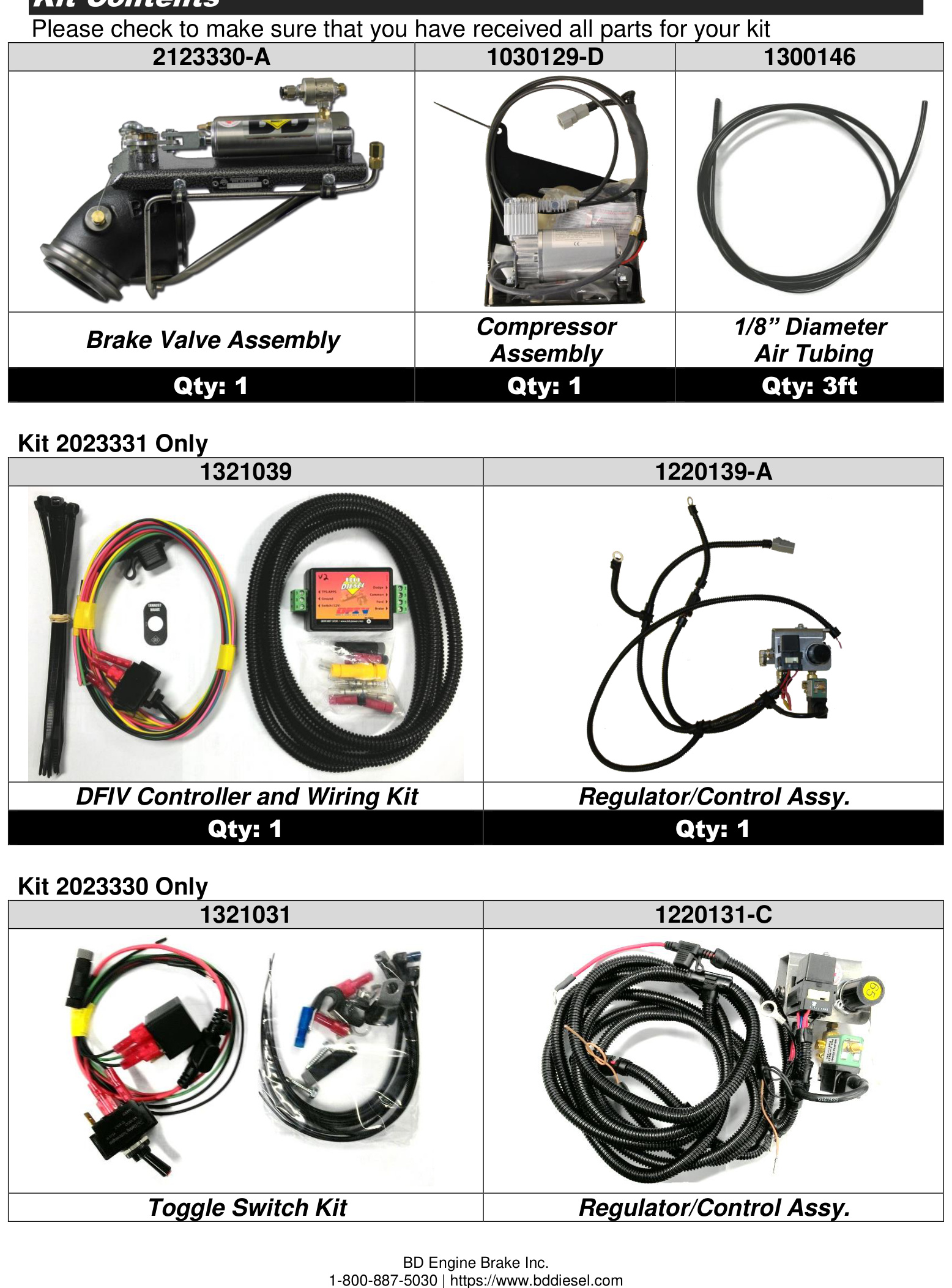
Before you begin, check that you have received all the parts for your kit.
- Brake Valve Assembly (P/N 2123330-A) — Qty 1
- Compressor Assembly (P/N 1030129-D) — Qty 1
- 1/8″ Diameter Air Tubing (P/N 1300146) — Qty 3 ft
- Kit 2023331 only: DFIV Controller and Wiring Kit (P/N 1321039), Qty 1; Regulator/Control Assembly (P/N 1220139-A), Qty 1
- Kit 2023330 only: Toggle Switch Kit (P/N 1321031), Qty 1; Regulator/Control Assembly (P/N 1220131-C), Qty 1
Optional Accessories
- Manual Transmission Shifter Switch Kit — P/N 1300210 or 1030900
- AutoLoc Converter Lock-up Kit — P/N 1030390
- Torqloc Converter Lock-up Kit — P/N 1030395
- Performance BD Valve Body — call for part number
- Brake Pressure Gauge Kit — P/N 1030050
Notes on Connectors
The kit includes a number of Posi-Tap™ connectors (Gray, Red, Black, Green or Yellow) to tap onto OEM wiring. It is important to select the correct color of connector so that it matches the gauge of the OEM wire it is being installed on. Using the incorrect connector could cause an inadequate connection and/or sever the OEM wire.
- OEM wire 18-22 ga → Gray or Red Posi-Tap™
- OEM wire 12-18 ga → Black Posi-Tap™
- OEM wire 10-12 ga → Green or Yellow Posi-Tap™
Though these connectors offer a quicker installation, the best option is to solder the wires and isolate the joints with heat shrink or liquid electrical tape, using proper soldering techniques for adequate connections.
CAUTION: The ground terminals of the vehicle’s batteries should be disconnected before performing any piercing or Posi-Tapping onto an ECM/PCM wire.
Tools Required
- Measuring tape or ruler
- Drill with 1/8″ and 3/16″ bits and a Unibit
- Crimping pliers
- Test light
- Socket set
- Small flat-tip screwdriver
Installation
WARNING: Raise and support the vehicle with a vehicle hoist or appropriate jack stands. Ensure the vehicle is safely supported before proceeding to reduce the possibility of damage or injury.
NOTE: To prevent damage to electronic components, it is recommended that both battery negative terminals be disconnected while working on the vehicle. Read this manual thoroughly before installing the exhaust brake.
Brake Valve Installation
- From underneath the vehicle, remove the down pipe-to-turbo elbow band clamp using a 10 mm socket. Support the down pipe, as it may drop down once the clamp is removed.
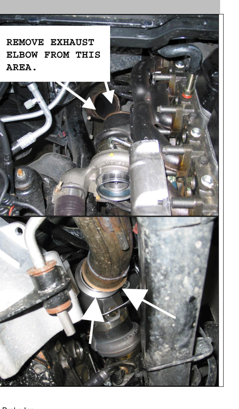
- In the engine bay, disconnect the intake air/pressure sensor harness behind the air filter and remove the plastic turbo air inlet tube. Loosen the band clamp that holds the factory exhaust elbow to the turbocharger and remove the exhaust elbow.
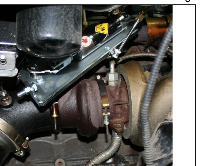
- Insert the exhaust brake valve assembly in place of the factory elbow and reinstall the turbo band clamp.
- Tighten all clamps that secure the brake to the flanges. Make sure the exhaust brake bracket is at least 1″ away from the exhaust manifold.
Air Compressor Mounting
- Remove the passenger-side front wheel and the plastic fender liner to gain access to the inner fender area.
- Install the supplied vibration-dampening foam tape to the bottom back side of the compressor bracket assembly.
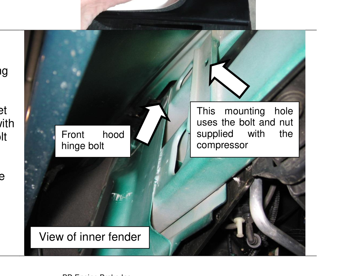
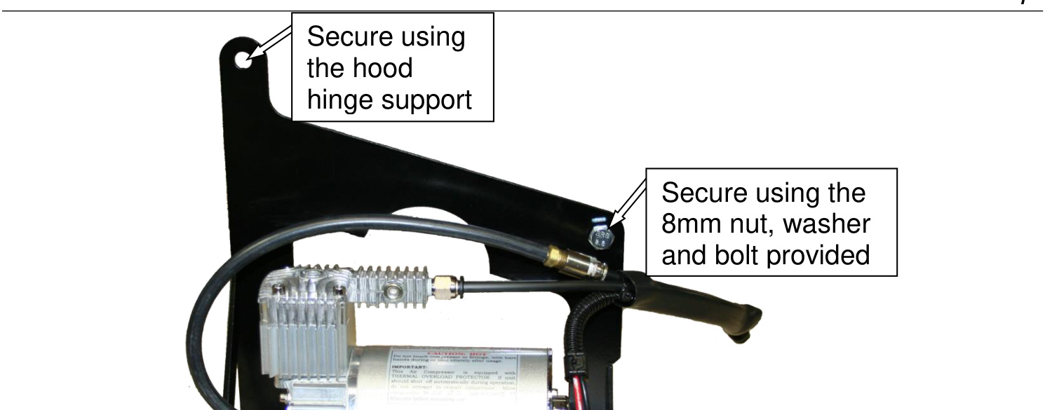
- Locate the two mounting points for the compressor. The bracket is designed to line up with the front hood hinge bolt and an existing hole in the inner fender. Remove the hood hinge bolt now to allow for installation of the compressor bracket.
- Feed the compressor air lines and wire through the fender into the engine bay (they will be connected later) and lift the compressor into place.
- Secure the compressor by reinstalling the hood hinge bolt through the compressor bracket, then install the supplied 8 mm nut, washer and bolt to hold the front of the bracket.
Regulator Assembly Installation
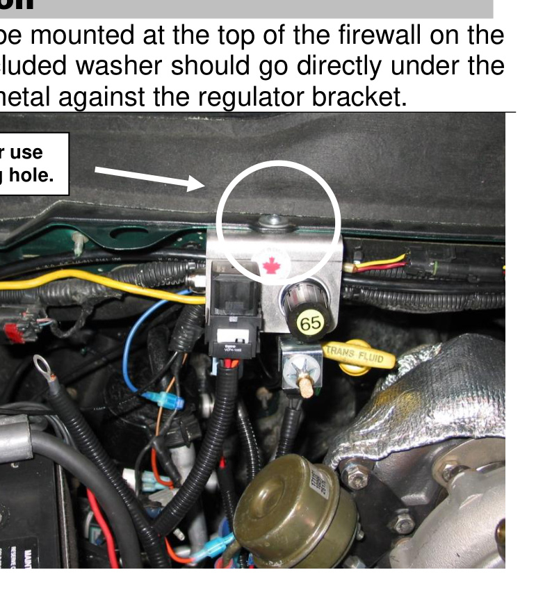
The air pressure regulator assembly mounts at the top of the firewall on the passenger side of the engine bay. The included washer goes directly under the head of the screw to sandwich the sheet metal against the regulator bracket.
- Locate the large oval hole on the passenger side of the vehicle near the upper cowling of the firewall. To the right of it, either drill a 3/8″ hole or use the existing hole by removing the factory plastic locking insert.
- Install the regulator assembly underneath the hole. The lock washer and flat washer should be installed on top of the plastic cowling, with the Phillips screw holding everything in place.
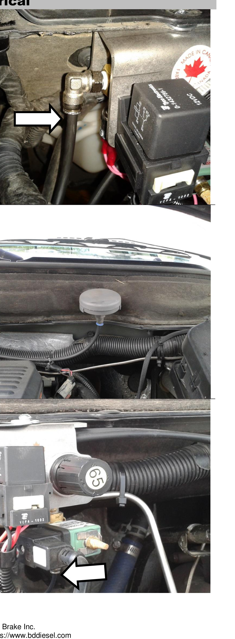
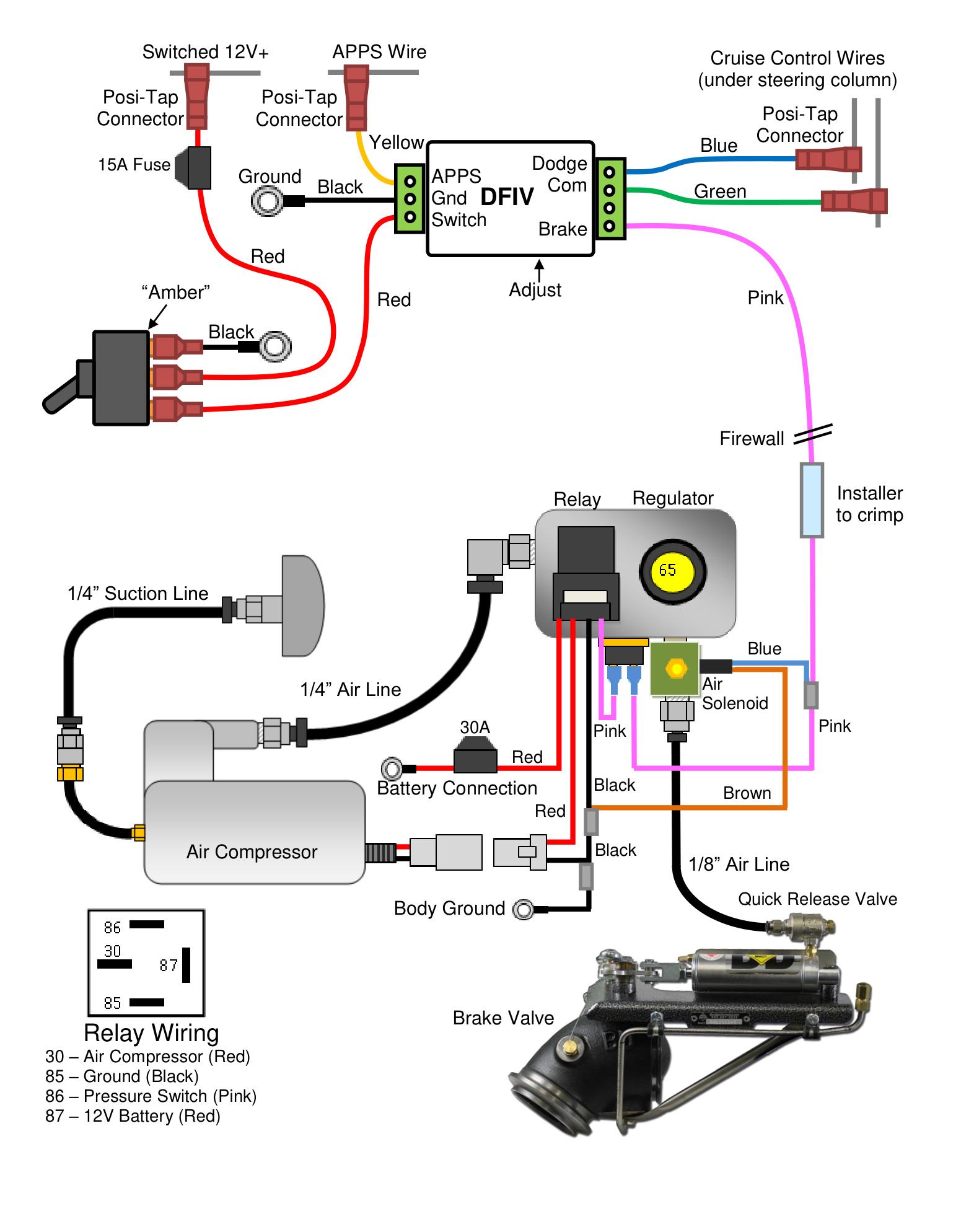
Regulator Plumbing and Electrical
- Connect the air pressure line from the pump to the inlet of the regulator assembly. This is the shorter of the two 1/4″ tubes from the compressor (the one without a fitting on the end); it connects to the passenger side of the regulator assembly, behind the relay. Trim the tube to length and insert it into the fitting.
- The other compressor line is the 1/4″ air suction line and comes with a pre-installed threaded adapter. Install the threaded filter supplied with the air pump into this fitting. The preferred mounting spot for the compressor air filter is just below the hood, using a factory mounting location for the sound-deadening material.
- Locate the 1/8″ tube supplied with the kit. Install it in the output of the air regulator assembly (on the bottom of the solenoid) and route it to the inlet port of the exhaust brake air cylinder. Trim to length and install in the 1/8″ fitting.
- Connect the main ground (the black wire with the ring terminal) to the body ground on the passenger side of the engine bay near the regulator assembly. Alternatively, it may be connected directly to the battery negative terminal.
- Connect the main power feed (the red wire with the ring terminal) to the passenger-side positive battery terminal clamp.
- Connect the two-pin gray connector from the regulator assembly to the air compressor.
Then continue with the in-cab wiring section that matches your model year (2006-07 or 2004.5-05). Refer to the wiring and plumbing diagram for your year for full detail.
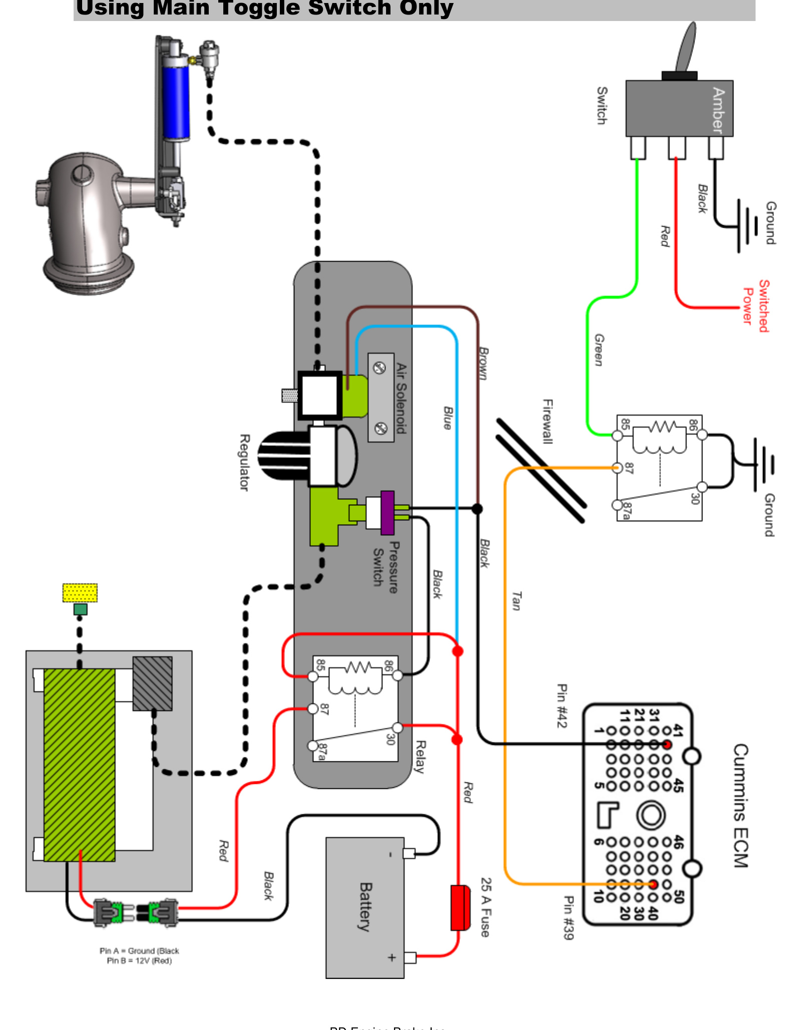
In-Cab Wiring (2006-2007)
ECM Activation Wire Install
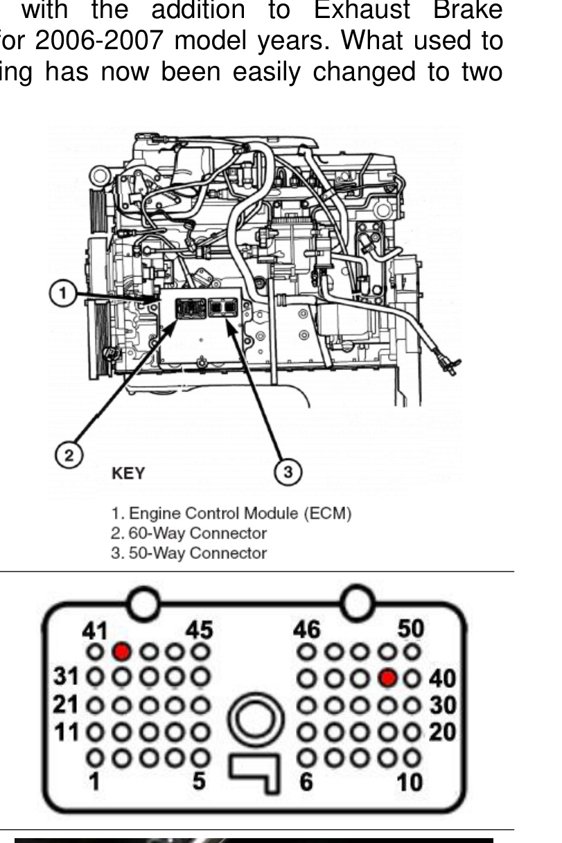
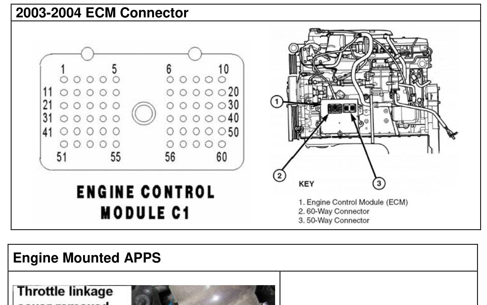
For 2006-2007 model years, exhaust brake activation runs through the Chrysler ECM, so in-cab wiring has been simplified to two wire leads going to the ECM. There are two ECM wiring blocks — one 60-pin connector and one 50-pin connector.
- Remove the 50-pin connector (#3 in the figure below).
- Locate Pin #39 (for the activation wire from the cab) and Pin #42 (for the black wire in the control harness). These pins have a factory plug in them that must be removed. Using needle-nose pliers and a straightened paper clip, insert the paper clip into the bottom end of the pin connector hole to poke the plug out the top, then pull it free with the pliers.
- Plug the two pre-crimped wire leads from the exhaust brake control harness into the ECM: insert the tan wire into Pin #39 and the black wire into Pin #42. They should snap into place.
- Re-install the ECM plug and secure the wiring loom using the supplied tie wraps.
After the ECM wiring, install the toggle switch (see Toggle Switch Install below) and the under-dash switch relay (2006-07 only).
In-Cab Wiring (2004.5-2005)
NOTE: If your truck is a 2006 or 2007, you do not need a DFIV module — that function is built into the factory programming. Use the 2006-2007 ECM wiring above instead.
DFIV Installation
- Mount the DFIV module in a secure location under the dash using the cable ties provided.
- Locate a grommet on the firewall and cut an opening in it to run the wiring through. Route the pink and yellow wires (for 2004) or just the pink wire (for 2005) through the firewall into the engine bay.
- Crimp the pink DFIV wire to the pink wire from the regulator & relay assembly, using the crimp connector with the clear plastic heat shrink. The yellow wire will be connected later.
- Attach the black ground wire to the “Gnd” terminal on the DFIV and attach its ring terminal to a good ground.
Accelerator Pedal Position Sensor (APPS) Wiring — 2004
There are two possible places to tap into the accelerator pedal sensor wiring: at the sensor itself or at the ECM. A Posi-Tap is included, but soldering this connection is recommended for longevity.
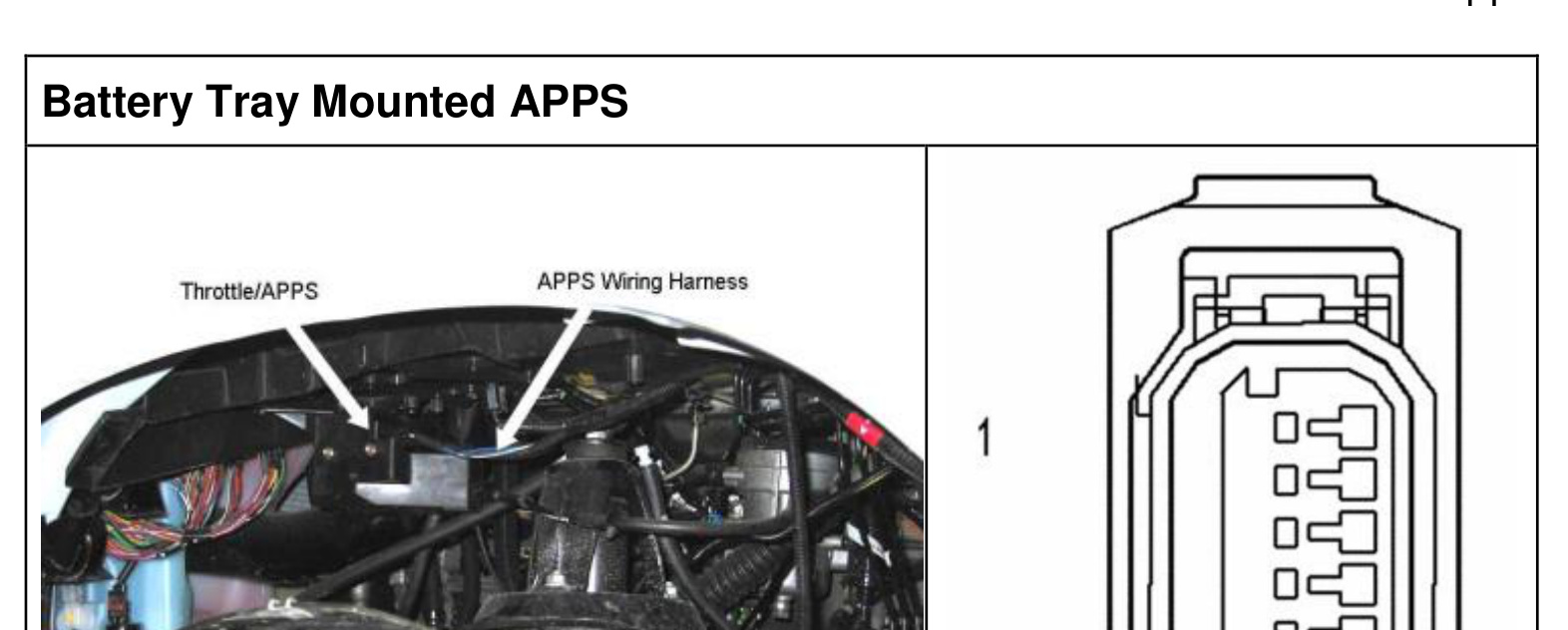
- At the sensor: route the yellow wire from the DFIV module to the accelerator pedal sensor (mounted on the side of the engine under a protective cover, or beneath the driver’s-side battery tray depending on model and transmission). Once connected, reconnect the APPS connector and reinstall the throttle linkage cover.
- At the ECM: use the wire color and pin location in the table below.
- 2004 Automatic — sensor on engine; APPS Pin 3 (BR/WT) → ECM C1 Pin 14 (BR/WT)
- 2004 Manual — sensor on battery tray; APPS Pin 5 (BR/WT) → ECM C1 Pin 14 (DB/WT)
NOTE: On 2004 manual-transmission trucks the wire color changes between the sensor and the ECM.
Accelerator Pedal Position Sensor (APPS) Wiring — 2005
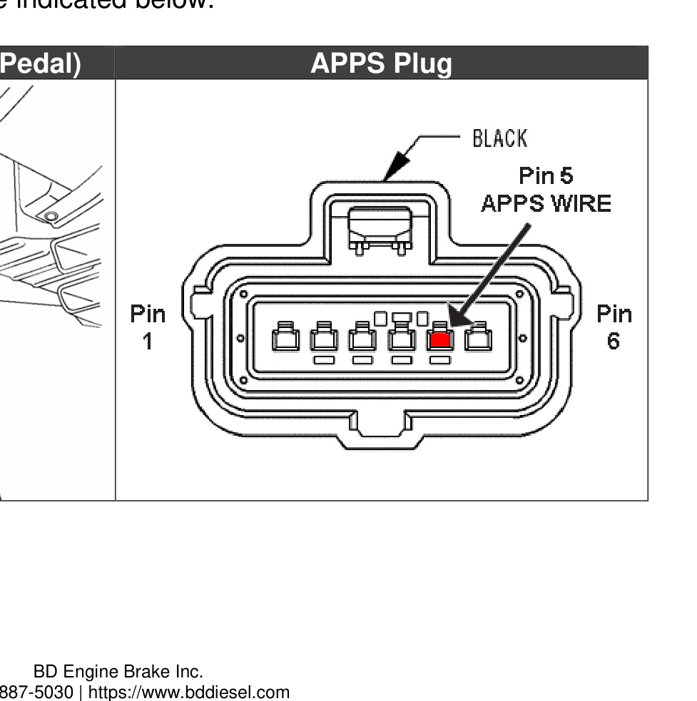
Route the yellow wire from the APPS terminal of the DFIV module to the accelerator pedal position sensor located on the accelerator pedal. Use a Posi-Tap to connect the yellow wire to the factory wire indicated — Pin 5 (APPS wire) on the pedal connector.
Cruise Control Wiring (2004.5-2005)
- Remove the lower steering column panel (remove the mounting screws and unsnap the panel from the instrument panel) to access the cruise control wiring harness.
- Under the dash, running vertically to the left of the steering column, locate the smaller wiring harness that runs out of the main harness. Remove some of the black electrical tape to access the smaller wire bundle.
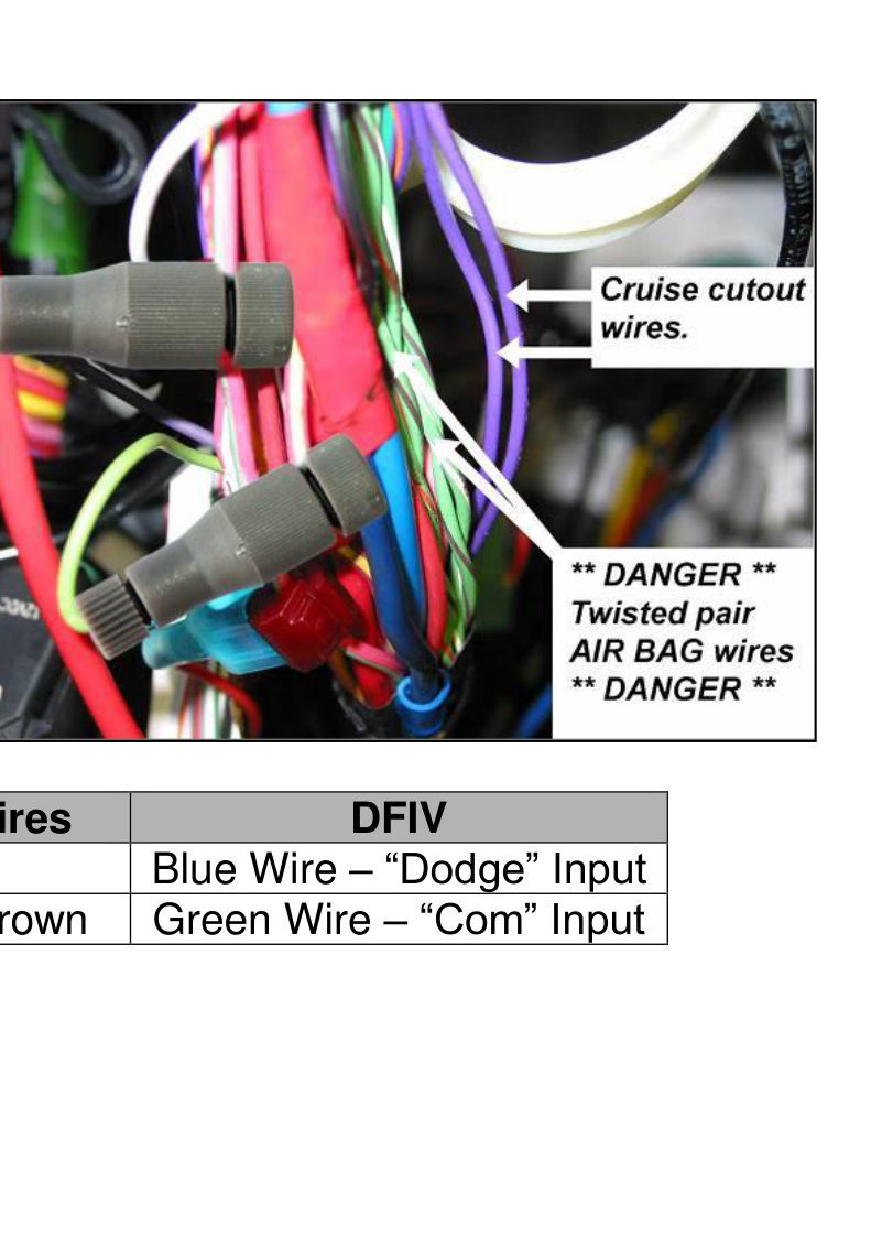
- Locate the small violet wire and install a gray Posi-Tap to it. Insert the blue wire from the “Dodge” terminal of the DFIV into this connector.
- In the same harness, locate the violet with brown tracer wire and install another gray Posi-Tap. Insert the green wire from the “Com” terminal of the DFIV into this connector.
DANGER: There are two sets of twisted-pair light-green-with-tracer wires in this bundle. Do NOT connect or test these wires — they are connected to the air bag system and the bag may deploy, causing damage and/or injury.
Toggle Switch Install
This step is required if you are using the main toggle switch. If you are using an optional shifter-mounted switch instead, skip to Optional Manual Shifter Switches below.
- Remove the attaching screws of the dashboard bezel and remove the covering trim by pulling rearward on the corners of the trim panels.
NOTE: Placing the transmission all the way into 1st/low gear and lowering the tilt steering all the way down allows for easier removal.
- Pull the left- and right-hand dash panels away from their secured positions and let them hang. Once the dash trim is removed, place it on a large working surface such as a table or workbench.
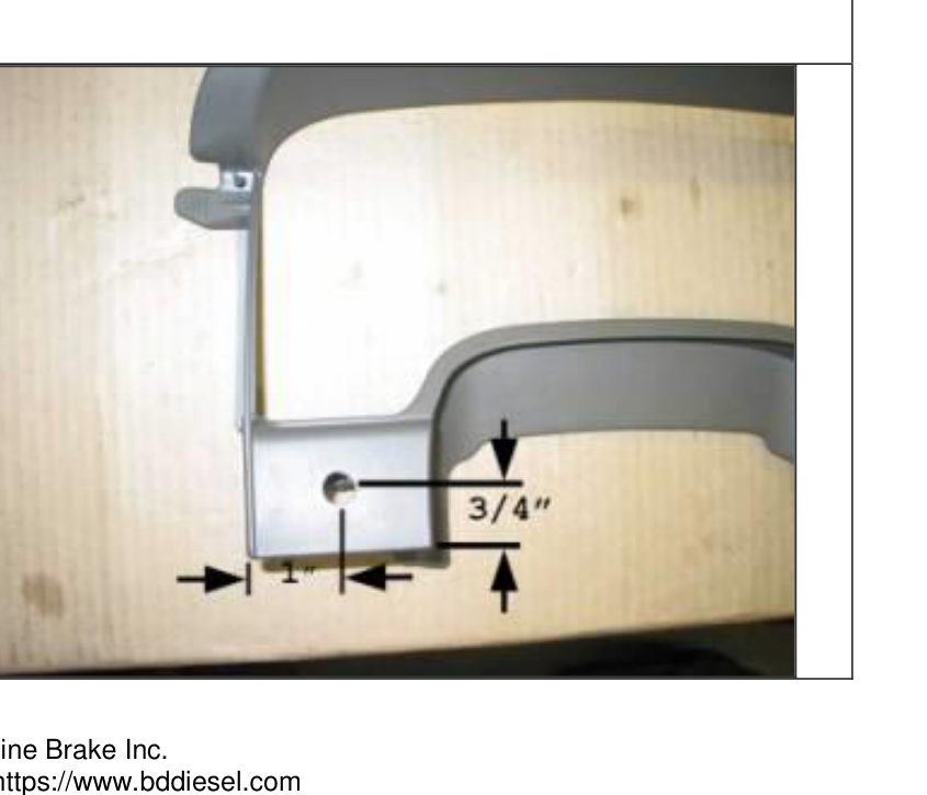
- Measure and mark a spot for the toggle switch 3/4″ up from the bottom edge of the dash panel and 1″ in from the left edge of the accessory panel.
- Drill a pilot hole with a 1/8″ bit, then enlarge the hole with a Unibit to exactly 1/2″.
NOTE: You may have to grind down part of the support rib on the back of the trim panel to accommodate the switch body.
- Install the switch into the drilled hole and secure it with the plastic lock ring. Reinstall the dash trim panels by reversing the removal procedure.
- Attach the switch ground wire to a good metal ground under the dash.
- With a test light, locate a switched 12 Volt power source (frequently a pink-with-white-tracer wire) and install the supplied black (12-18 ga) Posi-Tap™ to it, then attach the red fused wire from the switch to this Posi-Tap™.
- On 2004-2005 trucks, connect the remaining switch wire to the “Switch” terminal on the DFIV. On 2006-2007 trucks, it connects to the under-dash relay assembly (below).
Attaching the Switch Relay (2006-2007 Only)
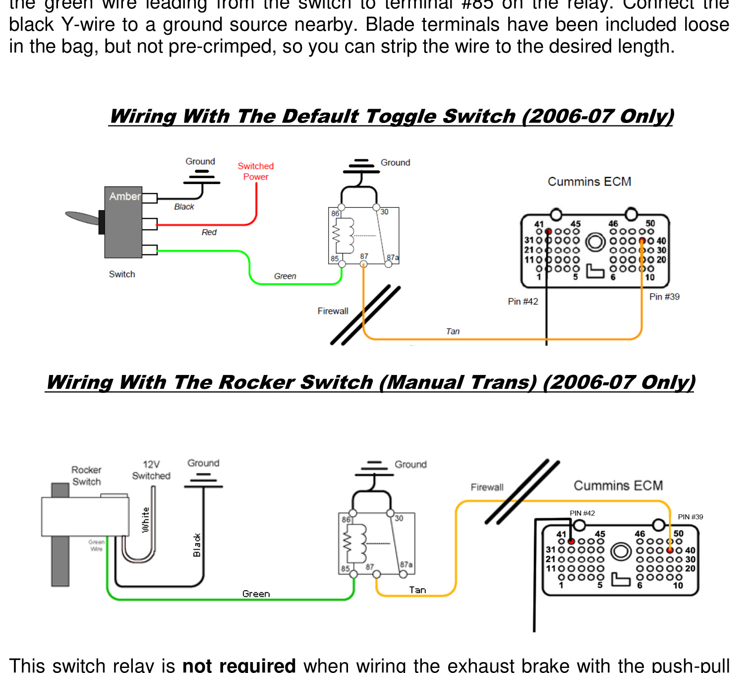
Because the 2006-07 exhaust brake controls run through the ECM, a relay kit must be installed (unless you are using the push-pull manual-transmission switch) so the light on the toggle or rocker switch can be lit while the brake is engaged. This relay comes pre-wired and is included in the main toggle switch kit.
- Connect the tan wire coming from the ECM to terminal #87 on the relay.
- Connect the green wire leading from the switch to terminal #85 on the relay.
- Connect the black Y-wire to a nearby ground source. Blade terminals are included loose (not pre-crimped) so you can strip the wire to the desired length.
NOTE: This switch relay is not required when wiring the exhaust brake with the push-pull style switch.
Optional Manual Shifter Switches
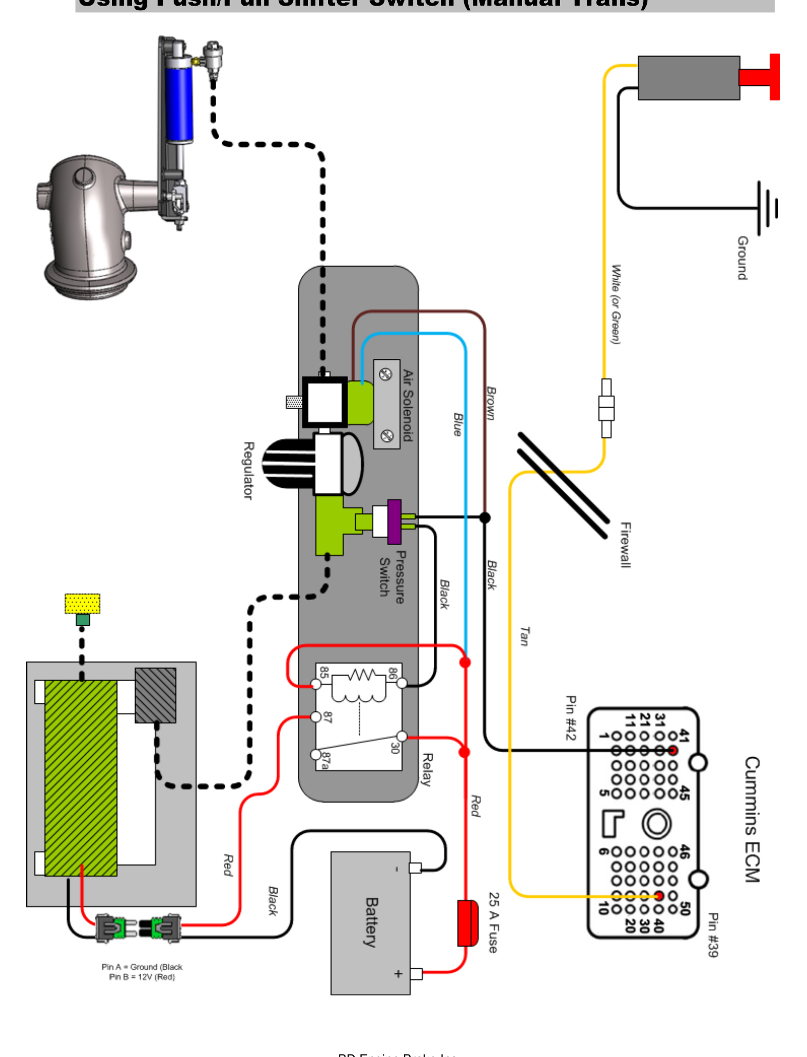
Push-Pull Style
- Mount the shifter switch onto the shift lever using the supplied clamp (5/8″ or 3/4″).
- Run the electrical cable down the shifter shaft, securing it with zip-ties or electrical tape, then route it under the carpet to the firewall and under the dash. Leave enough slack for proper shifting and to prevent the wire rubbing.
- At the end of the cable, cut off any excess and strip away about 1-2″ of the black rubber covering to expose the black and white (or green) wires, then strip the insulation from the wire ends.
- Connect the white (or green) wire to the tan brake activation wire leading to the ECM. Connect the black wire to a nearby ground source.
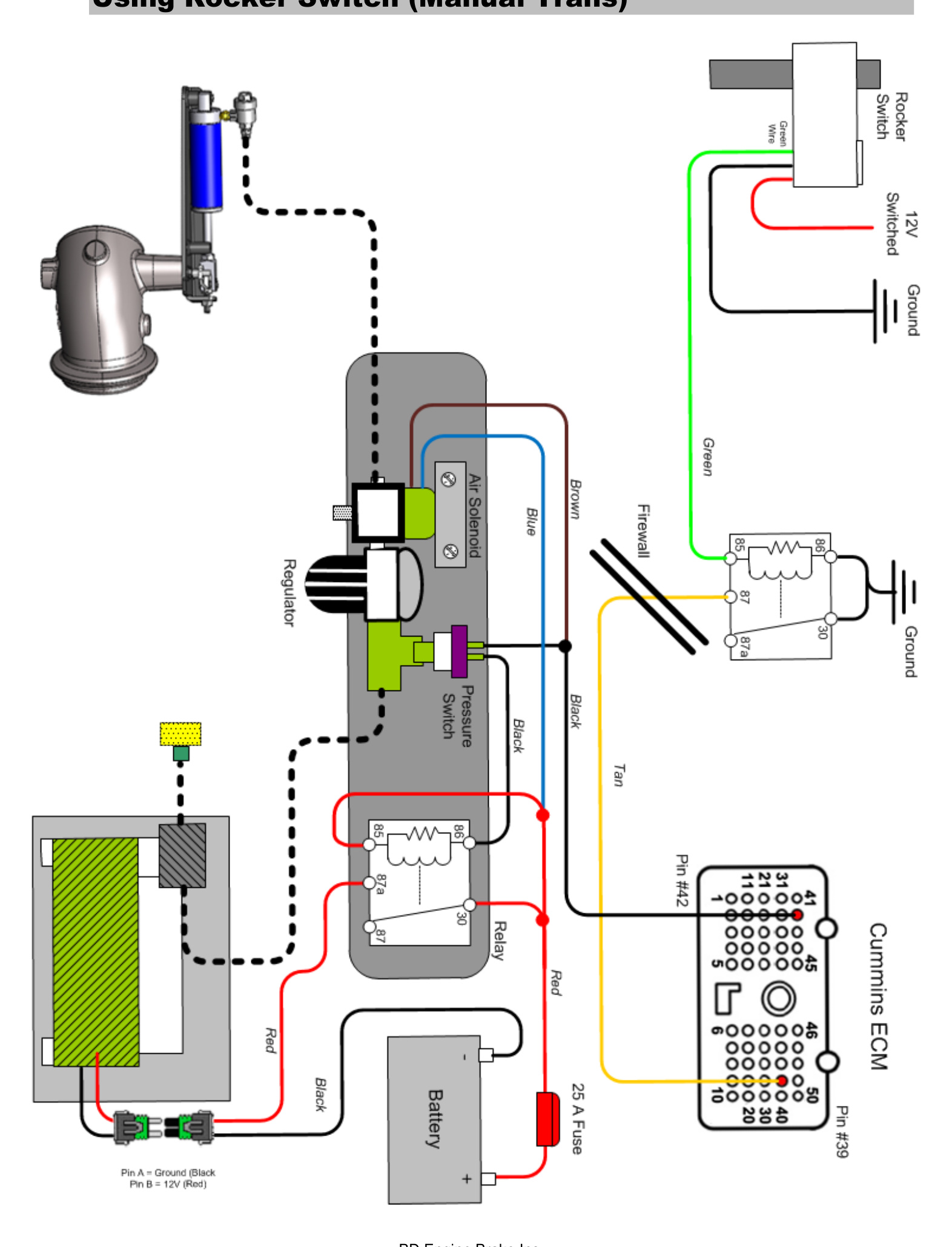
Rocker Switch Style
- Mount the shifter switch onto the shift lever using the supplied clamp (5/8″ or 3/4″) and route the cable under the carpet to the firewall and under the dash, as above.
- Strip about 1-2″ of the black rubber insulation to expose the black, white and green wires, then strip the wire ends.
- Connect the green 12V output wire to #85 on the switch relay (which leads to the tan brake activation wire going to the ECM).
- Attach the 5/16″ ring connector on the black ground wire to a good ground nearby.
- Locate one of the ignition-switched power fuses in the fuse panel under the steering column (traditionally a pink-with-white-tracer wire; verify with a voltmeter). Use the supplied fuse tap to supply ignition-switched power to the “Keyed 12 Volts” (white) wire of the rocker switch assembly.
Wiring & Plumbing Diagrams
DFIV Adjustment & Testing
For 2004.5-2005 trucks, the DFIV module must be calibrated so the exhaust brake activates correctly in relation to the throttle pedal.
- Connect one end of a test light to the “BRAKE” terminal of the DFIV module and the other end to a good ground.
- With the throttle at idle, turn the key to RUN and turn on the toggle switch (the switch should light up).
- Using a small flat-bladed screwdriver, turn the small adjusting screw in the DFIV module counterclockwise or clockwise until the test light just turns on.
- As the accelerator pedal is applied, the test light should turn off just as the throttle comes off idle — indicating proper calibration with the APPS. The light should activate again when the pedal returns to idle. If not, readjust the DFIV until it does.
CAUTION: The adjusting screw is a micro-switch that is very delicate — turn it in small adjustments.
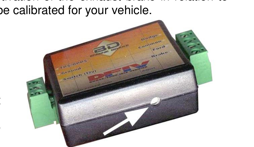
DFIV Terminal Reference
- TPS/APPS — the accelerator pedal position signal (sensor circuit #1, rising signal). Typically rises linearly from about 0.5V to 4.5V with throttle.
- Ground — connect to vehicle electrical ground.
- Switch (12V) — supplies 12V power to the DFIV from the toggle or shifter switch.
- Dodge — Dodge-only input; disables cruise control specifically for Dodge trucks.
- Common — common cruise input shared between the Dodge and Ford inputs.
- Ford — generic input; when the brake is activated, the connection between Ford and Common is severed.
- Brake — should read 12V when the key is in RUN, the brake switch is on and the throttle is at idle; no power if any of those conditions are not met.
Exhaust Back Pressure Testing
To test exhaust brake system pressure you need a minimum 0-100 psi pressure gauge. BD recommends the brake pressure gauge kit (P/N 1030050). You do not measure the air pressure in the system — only the exhaust backpressure, measured at the test port on the cast brake valve.
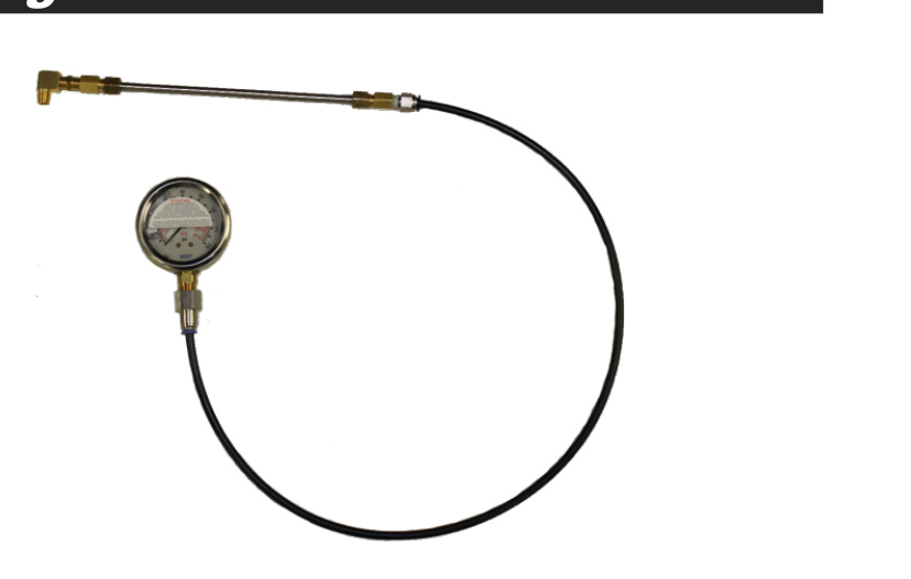
Idle Pressure Test
With the BD brake engaged and the engine at idle, check the exhaust backpressure at the test port on the brake valve.
- Below 13 psi at idle: The most common cause is an exhaust leak at the clamp joint or welds. Apply the brake and have a helper look for soot trails or visible leaks. Other culprits include an exhaust manifold leak, turbocharger gasket leak, turbocharger problem or an EGR issue.
- Greater than 25 psi: Adjust the stop bolt. Loosen the jam nut and lengthen the stop bolt towards the actuator to shorten the stroke distance. Turn only 1/4 rotation at a time, re-secure the jam nut and retest.
NOTE: The brake stop-bolt and regulator are preset at the factory and should not normally need adjustment. BD generally does not recommend adjusting the stop bolt — please consult BD before doing so, as it may void your warranty.
Off-Idle Pressure Test & Adjustment
The BD exhaust brake is a variable-orifice design, so at higher RPM the brake lever does not rest on the stop bolt. Off-idle backpressure is set by adjusting the air pressure regulator.
- Secure your pressure gauge where you can see it while driving (a long extension hose into the cab through an open window, or clipped under a windshield wiper, works well).
- Get the truck up to speed (a downhill grade or a load helps) and activate the exhaust brake. Note the maximum backpressure — you should get peak backpressure at higher RPM (try 3000 RPM in Drive).
- If you cannot reach the target backpressure (see the table below), first check for exhaust leaks at the clamps, manifolds, feed pipes, the back of the turbo and the down pipe. If all connections are sealed, use the adjusting regulator to increase backpressure.
- Turning the regulator clockwise increases pressure.
- Turning the regulator counterclockwise decreases pressure.
Small regulator adjustments can have a significant effect on off-idle backpressure.
Maximum back pressure by application:
- GM/Chevy 6.5 — 35 psi
- GM/Chevy Duramax — 55 psi
- Ford Powerstroke — 45 psi
- Dodge Cummins 1988-98 12V (without 60 lb springs) — 40 psi
- Dodge Cummins 1988-98 12V (with 60 lb springs) — 60 psi
- Dodge Cummins 1998 to current — 65 psi
HD spring part number is 1030060.
NOTE: Over the first two weeks, idle backpressure may rise due to initial carbon build-up inside the brake housing and on the butterfly. The stop bolt may need to be adjusted again to compensate.
CAUTION: Do NOT exceed the maximum back pressure value for your application. Exceeding it will force the exhaust valves open during the intake stroke, which could cause engine damage.
Maintenance
- To extend the life of the exhaust brake, do not operate the vehicle for extended periods without activating the brake. Activate it at least a couple of times a day to prevent carbon or rust build-up on the brake valve’s inner parts and to keep the butterfly valve from sticking.
- Inspect the hoses, wires, fittings and clamps on a regular basis for any deterioration, damage or leaks.
- If a problem arises, follow the diagrams in this manual — trace hoses and wiring, check continuity through electric components, and look for any disconnected lines.
Air Brake Troubleshooting Guide
This guide assumes the system uses a DFIV and a BD air compressor. If your system uses a microswitch for throttle activation, the air solenoid and pump operate the same way as with the DFIV.
When I let off the throttle, nothing happens
- Check whether the DFIV is powering its “Brake” output when the throttle is at idle and the brake switch and ignition are both on. Verify the DFIV has good power, ground and throttle signal, and check the DFIV adjustment. If these check out but the DFIV won’t power the “Brake” output, the DFIV is likely faulty.
- Check power and ground at the pump relay and make sure the air solenoid has a good ground.
- Verify that when the air solenoid is powered it allows air to flow from the #2 port out the #1 port.
- Check that the pump relay is powering the pump. If the pump has power but does not run, the pump is likely faulty. If power and ground are good at the relay but it does not click or power the pump, the relay is likely faulty.
The brake comes on but there’s little or no holdback
- Check that the torque converter stays locked up during deceleration. If it unlocks, engine RPM falls to idle when the throttle is released and the brake will be ineffective.
- Check off-idle brake pressure against the back pressure chart. If you are not getting maximum allowable backpressure, check for exhaust leaks — even a small leak can cause a significant drop. If no leaks are found, try adjusting the air regulator and check for air leaks in the brake system.
- Try downshifting more aggressively — more RPM gives more holdback.
- The transmission or torque converter could be slipping internally.
Everything seems to work, but the brake valve won’t close
- Check that air is reaching the brake air cylinder. If not, the air solenoid or quick-release valve is likely stuck, plugged or faulty — clean or replace as required.
- If air is reaching the cylinder, the cylinder or brake valve may be seized. Remove the clevis pin at the end of the cylinder rod and check whether the valve lever moves freely. If the lever moves freely, dismount the brake and clean the carbon out of it (replace the brake valve if cleaning does not help). If the lever is stuck, the cylinder is seized and must be replaced.
Other symptoms
- Air compressor runs in short bursts and brake is slow to apply: there is a restriction in the air system, normally in the regulator or air solenoid. Remove the fittings and clean out corrosion or debris with a pick, small brush, compressed air and WD-40 or similar lubricant.
- Air compressor runs continually: the pump relay is likely stuck on. Check the relay operation and replace as required.
- Brake is slow to release: debris or corrosion is restricting the quick-release valve or air solenoid — clean as required. The air solenoid could also be mounted too far from the brake.