
Installation instructions for the BD performance valve body, part #1030423, built for 2005-2007 Dodge 5.9L 24V Cummins trucks with the 48RE transmission. This guide lists the required tools and walks through valve body removal and installation for firmer, more reliable shifts.
Download the Original PDF Manual
IMPORTANT: Read all instructions before beginning the installation.
Tools Required
- Inch-pound torque wrench
- 7/16″, 1/2″ & 1 5/16″ sockets
- #25 Torx bit
- Combination wrench set including 7/16″ & 3/4″
- High-quality pressure gauge (0–300 psi)
- Voltmeter
- 6″ C-clamp
Additional Parts Required (Not Included)
- Mopar ATF+4
- 1 bottle of Red Lubegard (recommended)
Pre-Installation Testing
All diesel Rams should be tested prior to engine or transmission performance tuning. Check the transmission oil level prior to all work. Pressure testing will produce results that help determine the transmission’s ability to prevent the clutch surfaces from slipping. Slippage results in premature converter and transmission wear (soft or severe shifting, high transmission temperature).
NOTE: The transmission needs to be at operating temperature for these tests.
48RE Transmission Line Pressure
- Transmission in DRIVE, engine at idle — OEM: 55–65 psi; BD: 90–110 psi.
- Transmission in DRIVE, converter locked up @ WOT — OEM: 110–120 psi; BD: 170–200 psi.
Record your “before” and “after” shift points (RPM) for the 2nd–3rd shift under both normal driving and wide-open throttle.
IMPORTANT: If pressures and/or shift points are not to spec, the transmission must be repaired or serviced before any modifications.
Installation
- Pressure testing is accomplished by inserting a fitting and hose assembly with a good-quality gauge into the center 1/8″ port on the passenger side of the transmission. Leave the gauge attached for testing later.
- VERY IMPORTANT — Road test with the gauge in place and record pressures and shift-point RPMs before any modifications, to determine the condition of the transmission prior to installing this valve body. Pressure will only be indicated with the transmission in the Drive position.
- Secure the vehicle with wheel chocks and place the transmission in Neutral.
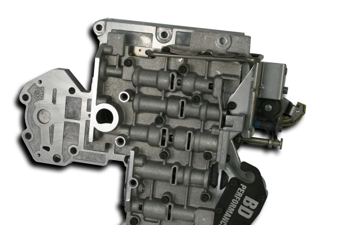
- Ensure the valve body has not been damaged in shipping and that it is the proper part number for your vehicle.
- Starting at the transmission, remove the shift cable from the manual lever.
- Rotate the shift lever to the rear of the vehicle to place the transmission in the PARK position.
Removing the TTVA and Valve Body
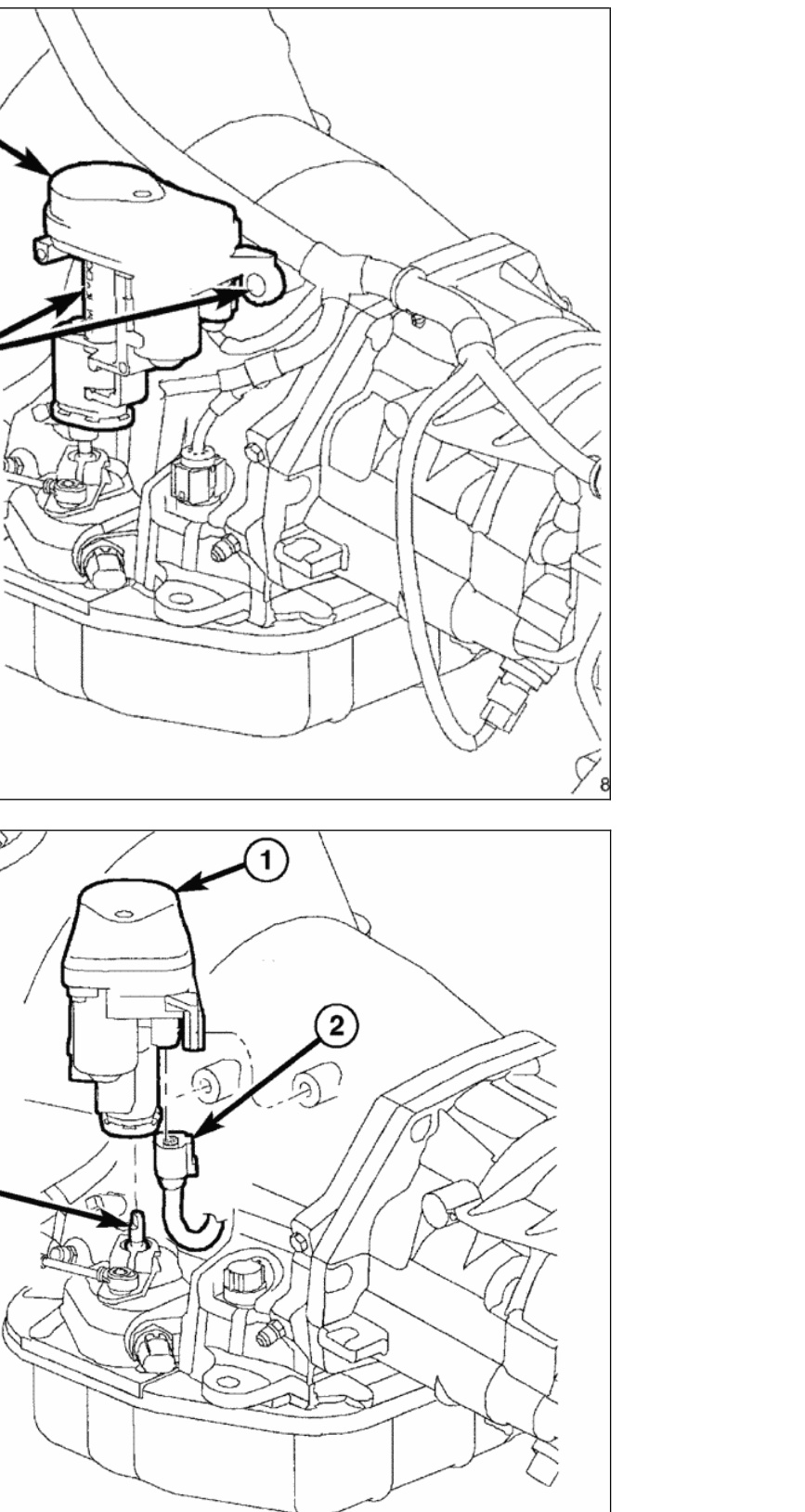
- Remove the two (2) bolts holding the TTVA motor to the transmission case.
- Allow the TTVA to rotate clockwise away from the transmission.
- Remove the wiring connector (#2) from the TTVA.
- Lift the TTVA straight upward and off of the throttle valve shaft.
- Loosen the shift lever bolt, then rotate the lever towards the front of the truck, shifting the transmission into the 1st / LOW position. This allows removal of the Park Rod E-clip without dropping the valve body.
- Remove the shift lever.
- Disconnect the wiring connectors from the Neutral Safety switch and the valve body, then remove the Neutral Safety switch from the transmission.
- Place a large drain pan under the transmission, remove the oil pan, drain the transmission oil and then remove the filter.
- Carefully remove the E-clip from the park rod, leaving the park rod in the transmission.
- Remove the 10 valve body bolts, remembering the location of the different bolts. The attaching bolts are different lengths and must be reinstalled in the proper location.
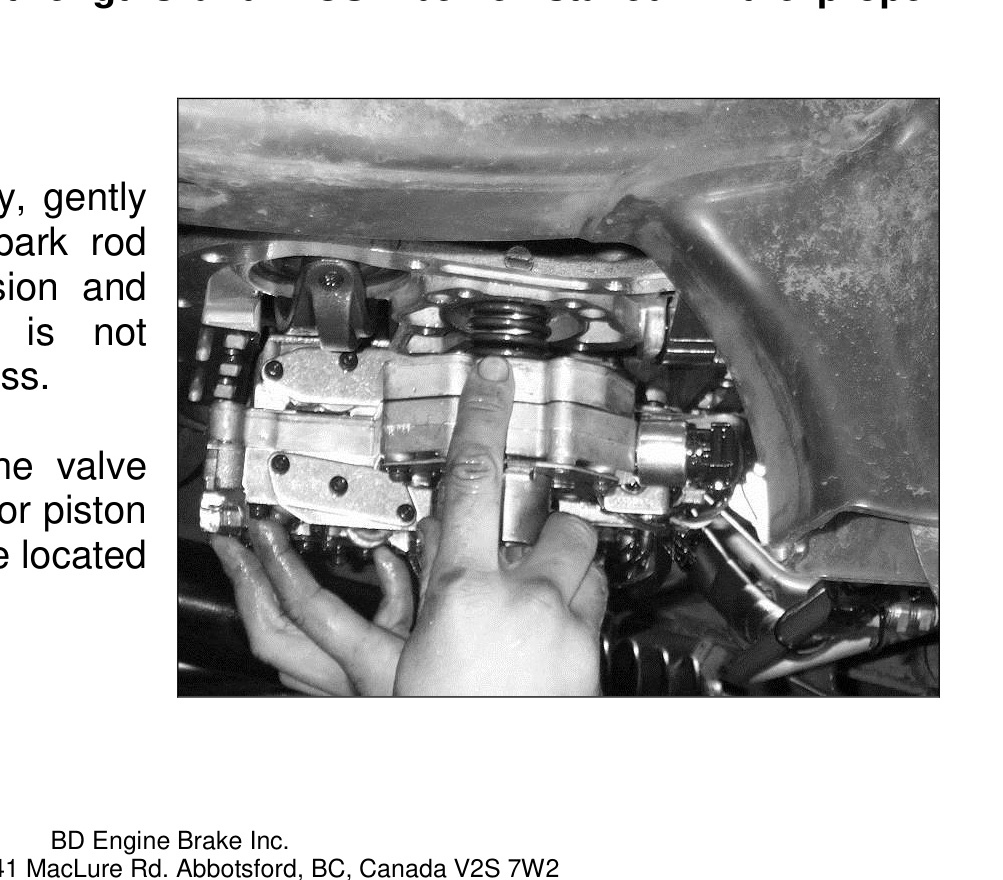
- When lowering the valve body, gently work it around so the park rod lever is left in the transmission, and ensure the electrical plug is not damaged in the removal process.
CAUTION: As you lower the valve body, watch for the accumulator piston and spring falling out. They are located above the governor solenoid.
2nd Gear Band Strut & Servo Spring
- This is the time to change the 2nd gear band strut to the heavy-duty one and install the 2nd gear servo spring we supply. First loosen the band adjusting screw lock nut with a 3/4″ wrench, then unscrew the adjuster until the stock strut can be removed.
- For the next step you will need a 6″ C-clamp. This clamp is available from AutoZone (#QRCC6) or from Schucks / O’Reilly’s (#648641). The cost is roughly $10.
- Using a 6″ C-clamp and a 1 5/16″ socket (or 32 mm), depress the servo piston guide into the bore of the transmission. This is a critical step and damage could ruin the transmission.
WARNING: DO NOT let anything score the bore or the shaft.
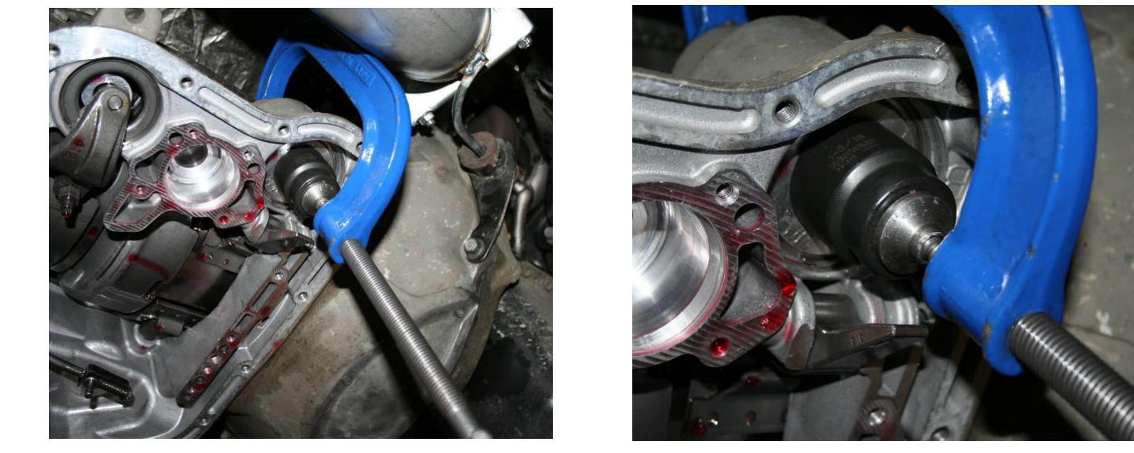
- Remove the retaining clip. DO NOT LOSE.
- Loosen the C-clamp to allow the servo piston guide to be removed from the bore. Remove the clamp, servo piston guide and spring.
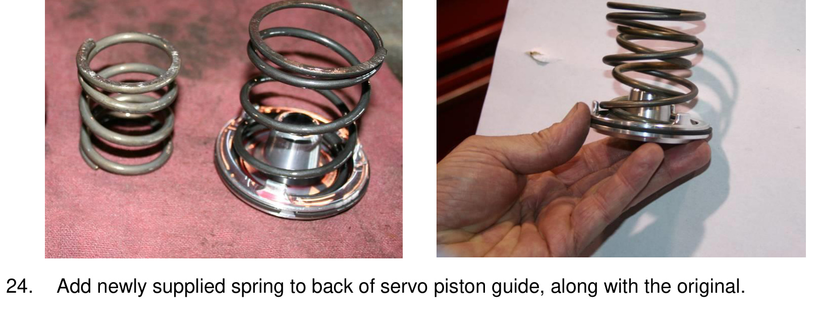
- Add the newly supplied spring to the back of the servo piston guide, along with the original spring.
- Re-install the servo piston guide into the bore with both springs. Hold the servo piston guide in place while slowly tightening the C-clamp. Tighten the C-clamp very slowly until the servo piston guide ring touches the bore taper. Help the servo piston guide ring into the bore with a small blunt screwdriver. If the ring binds or catches the retaining ring groove, lightly tap the servo piston guide to release it.
WARNING: DO NOT damage the servo piston guide ring.
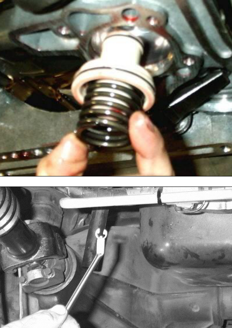
- Once the servo piston guide is depressed far enough, install the retaining ring. Once installed, you can remove the C-clamp.
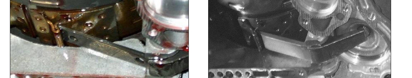
- Install the new BD strut with the tapered side down (towards the pan) and centered in the guides. Torque the band adjustment to 72 inch-lbs, then back it out 2 1/4 turns and tighten the lock nut. The air gap between the band lever and servo piston should measure 5/16″.
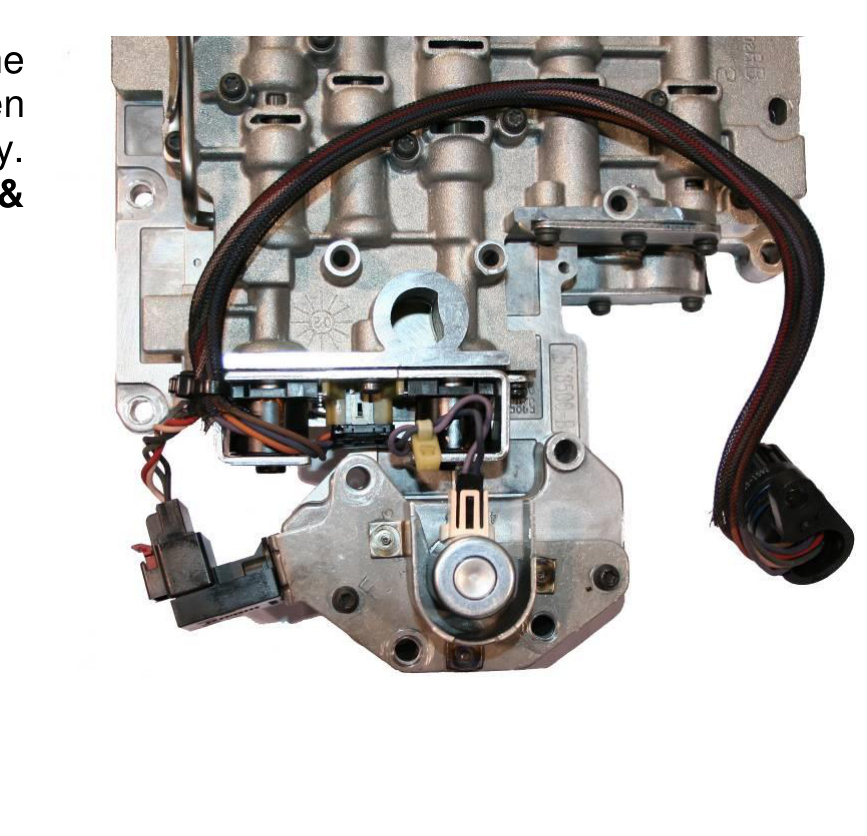
Transferring the Solenoid & Sensor
- From the old valve body, remove the electrical solenoid and sensor, then install them on the new BD valve body. We recommend that a new governor solenoid & pressure transducer be installed.
Pressure Transducer Modification
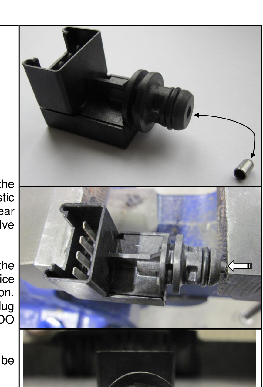
VERY IMPORTANT: A modification must be made to the pressure transducer switch (the black plastic style switch) on 2000–2007 model-year trucks before it is installed on the valve body.
To prevent over-pressure damage to the transducer, install a .040 orifice cup plug as shown in the illustration. The best method to insert the orifice cup plug is to squeeze it in gently with a vice (DO NOT use a hammer). Once installed, the orifice cup plug should be flush.
Installing the BD Valve Body
IMPORTANT: Before installing the BD valve body, lubricate the manual-shifting shaft and the O-ring on the electrical connector that fit into the transmission case.
- Rotate the shift lever all the way forward to place the valve body in the 1st / Low gear position, ready for later attaching of the park rod and E-clip.
- Place the accumulator piston and spring in the BD valve body. If you cannot balance these parts on the valve body, hold them in place with a supporting tool or wire until the valve body is installed.
- Once the valve body is in position, insert the park rod into the manual shift lever and hold the valve body in place with a couple of bolts.
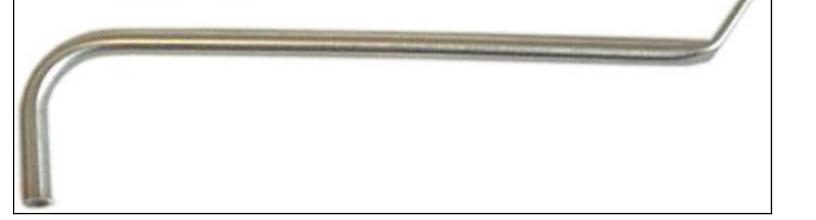
- Install the E-clip on the park rod using the flat, slotted end of the “hockey stick” tool.
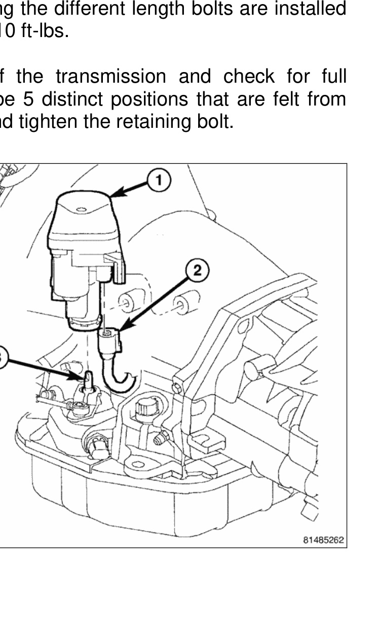
- Install the valve body mounting bolts, ensuring the different-length bolts are installed in the proper positions, and torque evenly to 10 ft-lbs.
- Install the manual lever on the outside of the transmission and check for full movement of the detent shift. There must be 5 distinct positions felt from Low to Park. Leave it in the Neutral position and tighten the retaining bolt.
Reinstalling the TTVA Motor
- It is now time to re-install the TTVA motor onto the throttle valve shaft:
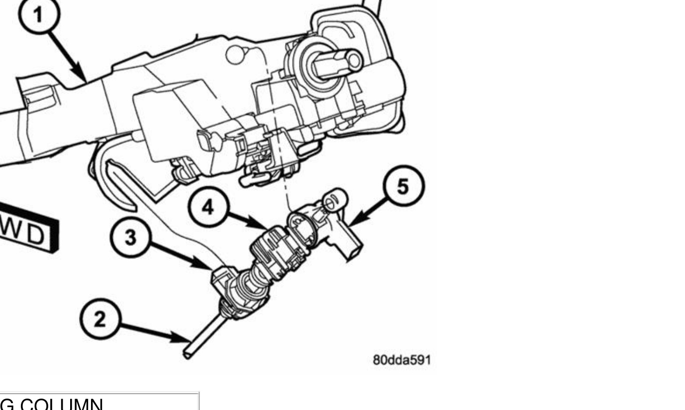
- Position the transmission throttle valve actuator (TTVA) over the throttle valve shaft (#3).
- Align the D-shaped opening in the bottom of the TTVA to the throttle valve shaft and install the TTVA onto the shaft.
- Install the wiring connector (#2) to the TTVA (#1).
- Rotate the TTVA (#1) to the transmission case and install the two bolts to hold the TTVA to the transmission.
- Tighten the bolts to 8.5 N·m (75 in-lbs).
- Initialize the TTVA: turn the key ON (KOEO), then leave the key in the ON position (KOEO) for 1 full minute.
- Install the neutral safety switch. The reverse lights at the rear of the vehicle should light when the shift lever is in the reverse position (key on).
- Install the new filter onto the valve body.
- We suggest you install a BD HD oil pan, which has extra oil capacity, cooling fins, a magnetic drain plug, and adds strength to the transmission case to prevent flexing.
- Install the shift cable to the manual lever on the transmission. Adjustment of the manual shift cable may be needed at this time. Ensure the wiring harness has some dielectric grease on it, then connect it — taking care not to bend the pins when attaching the plug.
Gearshift Cable Adjustment
THIS MUST BE DONE! Check the adjustment by starting the engine in PARK and NEUTRAL. The adjustment is CORRECT if the engine starts only in these positions, and INCORRECT if it starts in one but not both. If the engine starts in any position other than PARK or NEUTRAL, or will not start at all, the transmission range sensor may be faulty.
Gearshift Adjustment Procedure
- Shift the transmission into PARK.
- Release the cable adjuster lock tab (3) (underneath the steering column) to unlock the cable.
- Raise the vehicle.
- Disengage the cable eyelet from the transmission manual shift lever.
- Verify the transmission shift lever is in the PARK detent by moving the lever fully rearward. The last rearward detent is the PARK position.
- Verify positive engagement of the transmission park lock by attempting to rotate the propeller shaft. The shaft will not rotate when the park lock is engaged.
- Snap the cable eyelet onto the transmission manual shift lever.
- Lower the vehicle.
- Lock the shift cable by pressing the cable adjuster lock tab (3) downward until it snaps into place.
- Check engine starting. The engine should start only in PARK and NEUTRAL.
Filling & Final Road Test
- When just the valve body is replaced, fill the transmission with 8–9 quarts of ATF. When both the valve body and torque converter are replaced, 15–17 quarts are required.
IMPORTANT: After 8 quarts have been added, start the engine and shift through all gears, then check the transmission oil level with the shifter in Neutral. Top up and check as required. DO NOT OVERFILL!
- After the test drive, check the oil levels again. Air locks are common in this transmission.
- Road test the vehicle and check the wide-open shift points to ensure they are correct and to verify pressures.
NOTE: To recalibrate the TTVA motor, turn the key ON, then leave the key in the ON position (KOEO) for 1 full minute. A resistor is not used on 2005–07 48RE vehicles.