Complete installation instructions for the Pacific Performance Engineering (PPE) Diesel Fuel Lift Pump, part #113050000. This guide covers safety precautions, pump mounting, fuel-line connections, electrical wiring diagrams, recommended operating pressure and routine maintenance.
Download the Original PDF Manual
This pump is not legal for sale or use on emission-controlled motor vehicles.
Important Safety Precautions
CAUTION: Installation of this product should only be performed by those persons knowledgeable in the repair and modification of high-performance automotive fuel systems.
WARNING — Fuel system may be under pressure! Do not loosen the fuel system connections before relieving pressure. Some fuel may leak when loosening the connections. Eliminate potential fire hazards before loosening any fuel system connections. Always wear appropriate personal safety equipment, such as safety goggles and other apparel as needed, for protection from debris and sprayed fuel. Work in a well-ventilated area and keep a working fire extinguisher nearby. Extinguish any open flames and eliminate all sources of ignition in the area of the vehicle before proceeding with the installation.
Installation Guidelines
- Mount the fuel pump as close to the fuel tank as possible. The pump can be mounted on the vehicle frame or body sheet metal (use appropriate mounting hardware, including fender-style washers on sheet metal). The pump can be mounted in any direction — vertical positioning is not required.
- If possible, mount the fuel pump at the same height as the factory fuel line’s connection to the tank.
- If installing on a Duramax-equipped truck, install the fuel pump onto the shelf next to the fuel tank.
- Remove any aftermarket filters or straining components between the tank and the inlet of the fuel pump — the pump has a serviceable built-in straining filter. Use 1/2″ minimum line size for the 160 GPH fuel pump.
- Connect electrical power to the pump using appropriate soldering techniques or terminals. Use minimum 14-gauge wiring for all connections.
- Run the pump through an independent 10 amp fused circuit so it only comes on when the ignition is in the “ON” position. The pump must not be connected directly to the battery; an electrical relay can be used with the fuel-pump circuit. Ensure the pump’s negative wire (black) is properly grounded to the vehicle’s chassis (see the wiring diagrams below).
Installation Steps
With the ignition off and the engine cool, disconnect the negative battery terminal and relieve the fuel system pressure. Review the safety precautions above before you begin.
- If your truck is equipped with an OEM lift pump, continue with Step 2; if it is not, proceed to Step 3. Disconnect the existing pump fuel lines and plug the open line ends to prevent leakage and foreign matter from entering the fuel system. Remove the pump mounting screws and remove the existing pump.
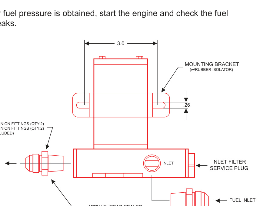
- Assemble the mounting bracket and the rubber isolator to the pump. Torque the bracket screw to 5–15 ft-lbs. Mount the new pump in a suitable place on the vehicle chassis using quality hardware (not supplied) — refer to the figure below for mounting-hole locations. Replace the existing fuel lines as necessary to line up with the new pump.
CAUTION: Use common sense when routing fuel lines and electrical harnesses. Keep them away from hot exhaust components and/or moving parts and properly secure lines to prevent chafing or abrasion. Fuel lines should never be routed inside the passenger compartment. It is also recommended that all fuel lines be routed on the inside of the chassis frame rails, as close to the fuel tank as possible.
- Connect and tighten the fittings on the inlet and outlet fuel lines (see the figure below). Use thread sealer (not supplied) on the fitting threads.
- Connect electrical power (12 VDC) to the pump as described in the installation guidelines above.
CAUTION: Route all electrical wires clear of moving suspension, driveline or exhaust components. Protect the wires from abrasion and road obstructions.
- If not previously equipped, attach a fuel pressure gauge to the fuel system. Operating pressure is 4–8 psi with the engine idling; pressures are not user-adjustable.
- Reconnect the battery. Turn the ignition to ON (without starting the engine) and check for fuel pressure after allowing the pump to run for several seconds. If no pressure registers and you have found no leaks, turn the ignition OFF and check all fuel and electrical connections to determine the cause.
- Once steady fuel pressure is obtained, start the engine and check the fuel system for leaks.
WARNING: If any leaks exist, shut the power off immediately and repair before continuing.
Maintenance
Clean the inlet strainer filter a minimum of once per year (more often when operating in dirty environments). Remove it by loosening the filter service plug and removing the element. Clean the filter element with solvent and compressed air, lubricate the O-ring, and reinstall the filter with the service plug. Tighten the plug to 5–15 ft-lbs of torque.
WARNING: Be sure the fuel level is very low and have an approved container with funnel ready to capture leaking fuel nearby. Fuel may exit the service plug and completely drain the fuel tank or cell.
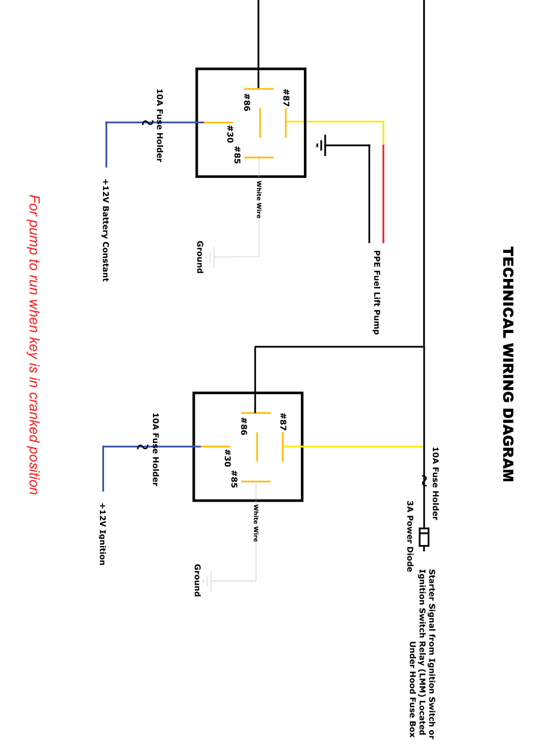
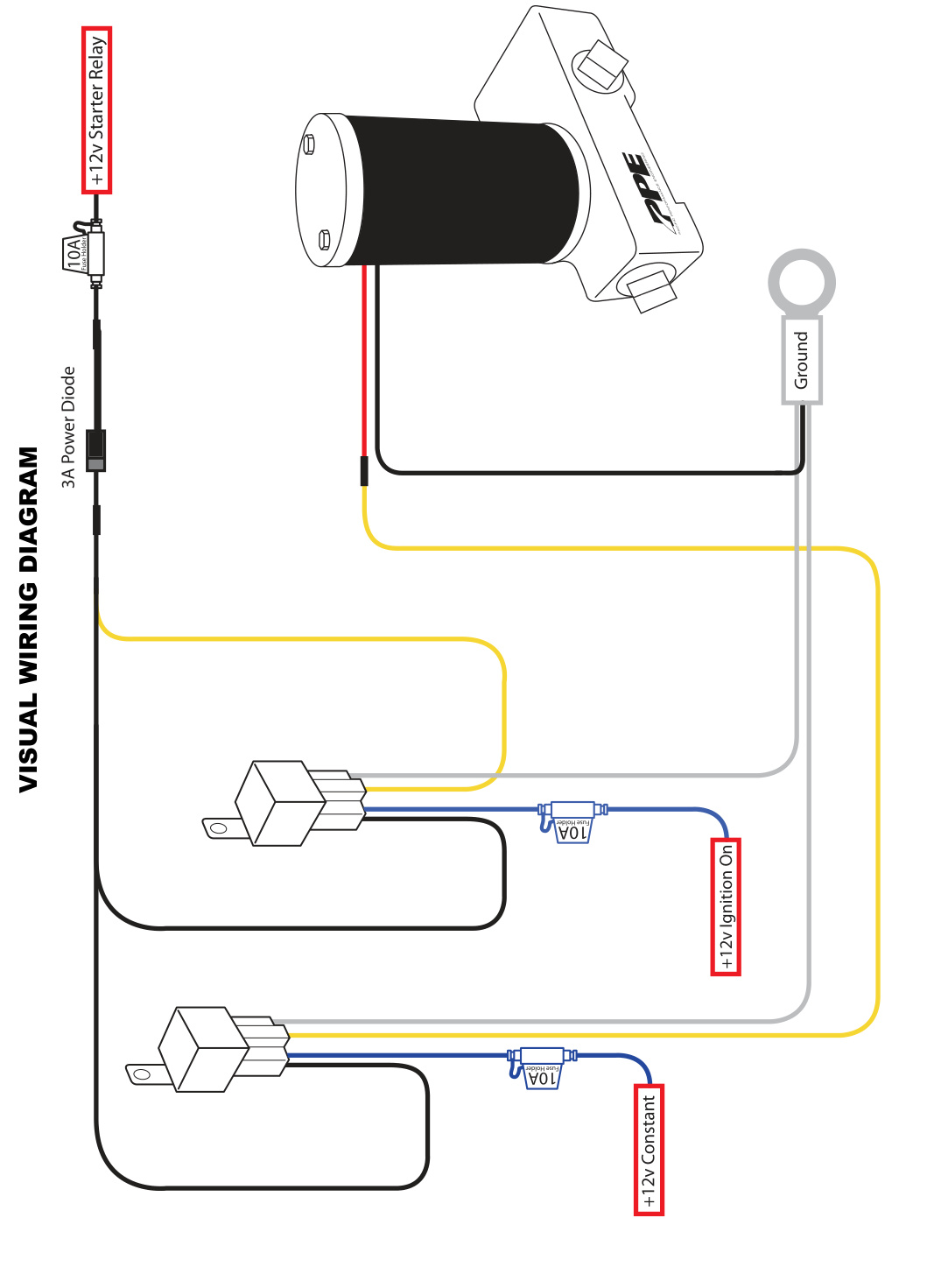
Wiring Diagrams
Wire the pump through a relay on an independent 10 amp fused circuit so it runs only when the key is in the cranked or ON position. Refer to the diagrams below.