Installation guide for the PPE Dual Fueler CP3 pump kit, part #113061100, for LB7 Duramax trucks. Adding a second CP3 injection pump supplies the extra fuel volume needed for high-horsepower builds. This guide covers the supplied parts, control module and high-pressure fuel-line routing.
Download the Original PDF Manual
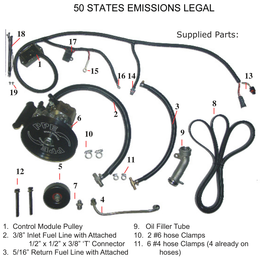
This Dual Fueler kit is 50-state emissions legal.
IMPORTANT: Throughout this guide, items are referred to by their kit part number (for example, “#4” is the High Pressure Steel Fuel Supply Line). Please note these part numbers — they are used in the installation descriptions below.
Kit Contents (Supplied Parts)
- 1. Control Module Pulley
- 2. 3/8″ Inlet Fuel Line with attached 1/2″ x 1/2″ x 3/8″ ‘T’ connector
- 3. 5/16″ Return Fuel Line with attached 5/16″ x 5/16″ x 5/16″ ‘T’ connector
- 4. High Pressure Steel Fuel Supply Line
- 5. Idler Pulley with attached parts (2002–04 models only — see Appendix C)
- 6. Assembled CP3 Pump, wheel and bracket
- 7. Fuel Rail Fitting
- 8. #6 Rib Belt
- 9. Oil Filler Tube
- 10. 2 × #6 hose clamps
- 11. 6 × #4 hose clamps (4 already on hoses)
- 12. 2 × M10-1.5 x 100 bolts with 2 washers
- 13. Control Module Internal Engine Pump connectors
- 14. Control Module Dual Fueler connector
- 15. Control Module +12V (red wire)
- 16. Control Module ground (black wire)
- 17. Control Module 10A fuse
- 18. Control Module harness tie straps
- 19. Control Module mounting screws
Torque Specifications
- Idler pulley (#5) into engine bracket — 27 lb-ft
- Dual Fueler bracket assembly to A/C compressor (#12 bolts) — 37 lb-ft
- #4 High Pressure line nuts (both ends) — 30 lb-ft
- Replacement Oil Filler Tube (#9) bolts — 15 lb-ft
- Fuel injection pump drive pulley nut (Appendix B) — 52 lb-ft
Before You Begin
If the Dual Fueler bracket and pulley are not already assembled on the CP3 pump (#6), assemble them first — see Appendix B at the end of this guide.
NOTE: This guide covers 2002–2004 LB7 trucks. For 2001 models, the idler-pulley location and belt routing differ — see Appendix C.
Installation
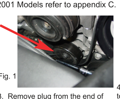
Step 1 — Install the idler pulley (2002–04)
On 2002–04 models, remove the belt and install the #5 Idler Pulley in the existing threaded hole on the engine bracket as shown. Torque to 27 lb-ft. (2001 models: refer to Appendix C.)
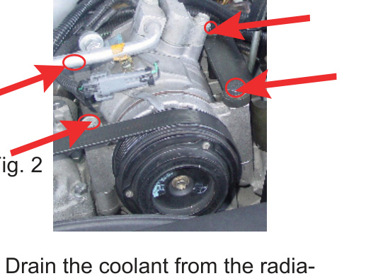
Step 2 — Move the A/C compressor
Remove the 4 A/C bolts as shown and set the A/C compressor to the left of the engine so you can access the fuel rail below.
Step 3 — Install the fuel rail fitting
Remove the plug from the end of the fuel rail using an E500 (used on seatbelt bolts) Torx wrench or socket, then install #7, the Fuel Rail Fitting.
IMPORTANT: Early-model LB7 trucks may have a block-off plate behind the Torx plug fitting. If so, remove this block-off plate and drill it out to the same size as the supplied fuel rail adapter fitting.
Step 4 — Clear access and start the high-pressure line
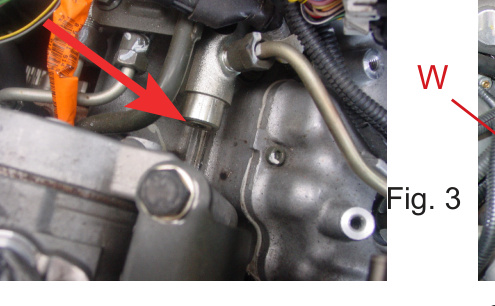
Drain the coolant from the radiator drain plug. Remove the alternator. Remove the EGR by first disconnecting the in and out hoses. Remove the Water Line (W) so you can access the #4 steel high-pressure line later, once the A/C compressor is back in place and the Dual Fueler is installed.
Attach #4, the steel high-pressure line, but do not torque it yet. Route it so it will lay under the A/C compressor.
Step 5 — Mount the Dual Fueler assembly
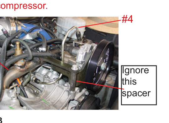
Place the A/C compressor back into its original position. Set #6, the Dual Fueler assembly (bracket with pump), on top of the right A/C compressor bolt holes and use the #12 bolts to attach the Dual Fueler bracket assembly to the A/C compressor. Torque to 37 lb-ft. Save one of the original A/C bolts for the next step.
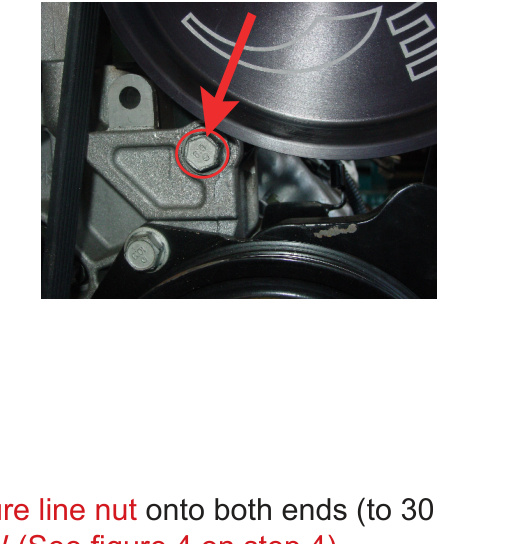
Step 6 — Install the lower bracket bolt
Install one factory A/C bolt (removed from the top of the A/C unit) into the bottom of the Dual Fueler bracket.
Step 7 — Torque the high-pressure line and reinstall the water line
Torque the #4 high-pressure line nut onto both ends to 30 lb-ft. Then re-install the Water Line (W) (see Fig. under Step 4).
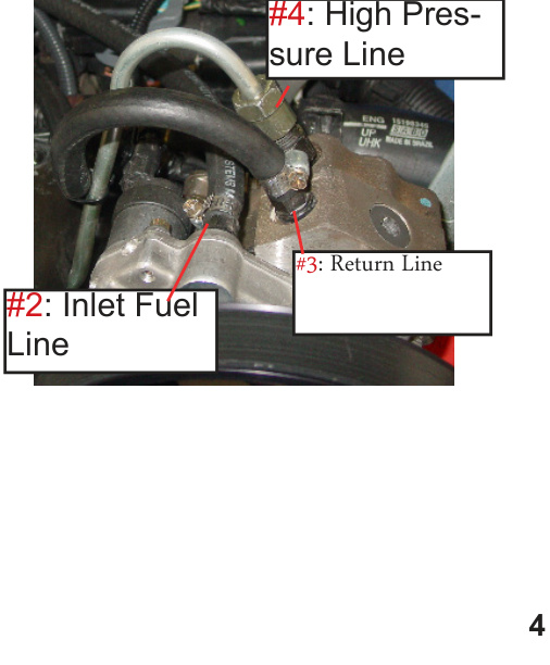
Step 8 — Connect the fuel lines
Attach the lines by part number as shown:
- #2 — Inlet Fuel Line
- #3 — Return Line
- #4 — High Pressure Line
Step 9 — Locate the fuel supply hose
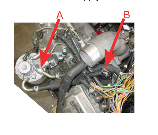
Follow the flow-direction arrow (A) exiting from the fuel filter housing in order to locate the fuel supply hose (B).
Step 10 — Splice in the inlet ‘T’ connector
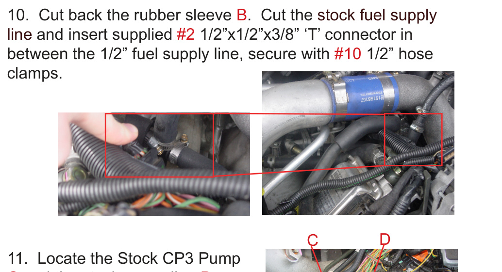
Cut back the rubber sleeve (B). Cut the stock fuel supply line and insert the supplied #2 1/2″ x 1/2″ x 3/8″ ‘T’ connector in between the 1/2″ fuel supply line. Secure with #10 1/2″ hose clamps.
Step 11 — Splice in the return ‘T’ connector
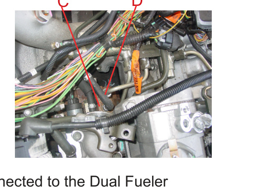
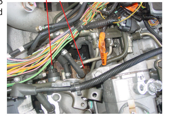
Locate the stock CP3 pump (C) and the stock return line (D) from the stock CP3 pump. Cut the rubber hose and insert the #3 5/16″ x 5/16″ x 5/16″ ‘T’ connector. Use #11 hose clamps to secure.
NOTE: All three lines should now be connected to the Dual Fueler pump and to the engine in the correct spots.
Wiring & Control Module
Steps 12–13 — Splice the engine pump connector
Locate the stock CP3 pump (C) from Step 11 and the electronic control wire harness (E). Unplug wire harness E. Plug harness E into #13, then plug the other end of #13 back into the stock CP3 pump C.
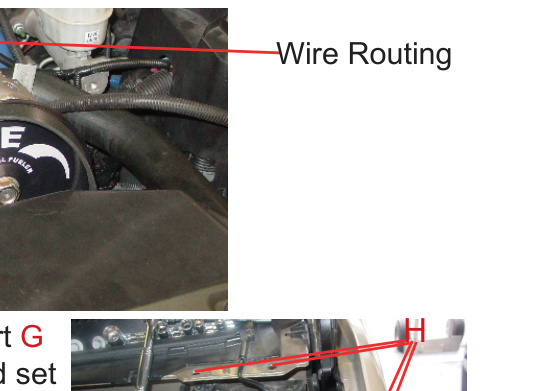
Step 14 — Route the control module wiring
Route the #1 Control Module wiring from the stock CP3 pump (C) as shown and attach to the other wiring with #18 tie straps. Connect #14 to the back of the Dual Fueler CP3 pump.
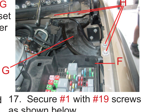
Step 15 — Remove the metal support and fuse box cover
Temporarily remove Metal Support (G) by removing the 4 bolts (H); set them aside. This lets you remove the fuse box cover (F) — the #1 Control Module will be tucked inside the fuse box cover F.
Step 16 — Place the control module
Remove the fuse box cover (F) and place #1 (Control Module) as shown.
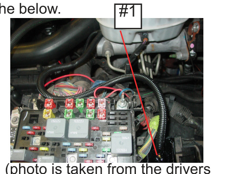
Step 17 — Secure the control module
Secure #1 with the #19 screws as shown.
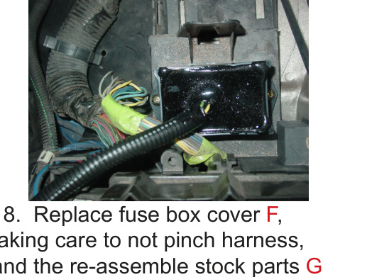
Step 18 — Reassemble the fuse box and support
Replace the fuse box cover (F), taking care not to pinch the harness, and reassemble the stock parts G and H as shown in Step 15.
Belt, Oil Filler & Power
Step 19 — Replace the oil filler tube
Remove the original oil filler tube and install #9, the Replacement Oil Filler Tube, to allow for belt clearance. Assemble with the original bolts and torque to 15 lb-ft.
Step 20 — Route the replacement belt
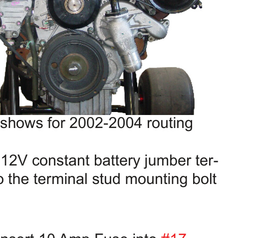
Route the #8 Replacement Belt as shown for 2002–04 models. (For 2001 models, refer to Appendix C.)
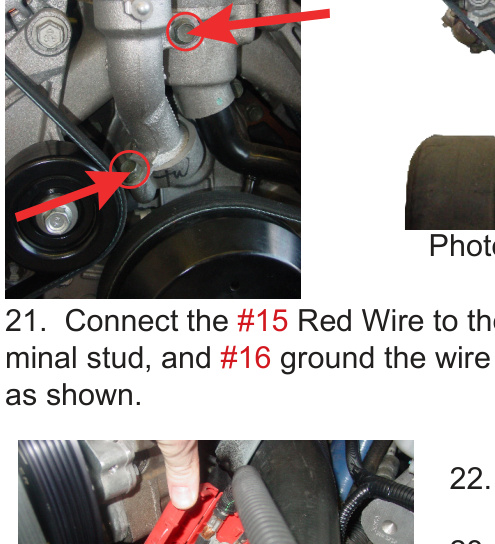
Step 21 — Connect power and ground
Connect the #15 red wire to the 12V constant battery jumper terminal stud, and ground the #16 wire to the terminal stud mounting bolt as shown.
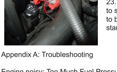
Step 22 — Install the fuse
Insert the 10 Amp fuse into #17.
Step 23 — Prime and start
The engine should now be ready to start. Prime the fuel filter pump to bleed air from the system, then start the engine.
Appendix A: Troubleshooting
- Engine noisy / too much fuel pressure: Check that the fuse is good and seated in the controller’s fuse holder, and that all power connections are secure. Confirm the connectors for both pumps are fully plugged in.
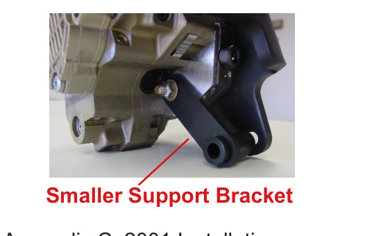
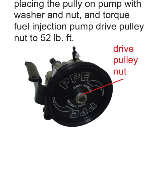
Appendix B: Fuel Pump with Bracket Assembly
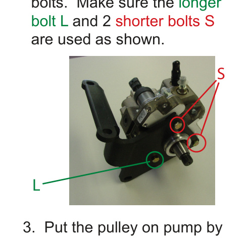
If the bracket and pulley are not already assembled on the CP3 pump, assemble them as follows:
- Install the main bracket and insert the 3 supplied bolts. Make sure the longer bolt (L) and the 2 shorter bolts (S) are used as shown.
- Install the smaller support bracket and secure it with a washer and nut on the back of the pump. Secure the other 2 bolts (S) with a washer and nut on the back of the pump.
- Put the pulley on the pump, placing it on with the washer and nut, and torque the fuel injection pump drive pulley nut to 52 lb-ft.
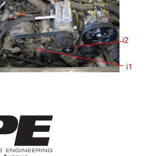
Appendix C: 2001 Installation
For 2001 installs, move the factory idler pulley from location I1 to location I2. No other idler pulleys are required. Route the belt as shown.