Installation guide for the PPE Dual Fueler CP3 pump kit, part #113063500 (and #113067000), for LBZ and LML Duramax trucks. Adding a second CP3 injection pump supplies the extra fuel volume needed for high-horsepower builds. This guide covers kit contents, the pump and bracket installation, fuel-line routing, the high-pressure valve, controller wiring and the replacement serpentine belt.
Download the Original PDF Manual
WARNING — Disconnect the batteries first. Disconnect both batteries before beginning. You will be working around the fuel system and engine accessory drive. Relieve fuel system pressure, work in a well-ventilated area, keep a working fire extinguisher nearby, and eliminate all sources of ignition before opening any fuel line.
NOTE: Throughout this guide, part numbers are referenced by their kit-contents item number (e.g. #2, #5, #11). Use the Kit Contents diagrams below to identify each part before you begin.
Kit Contents
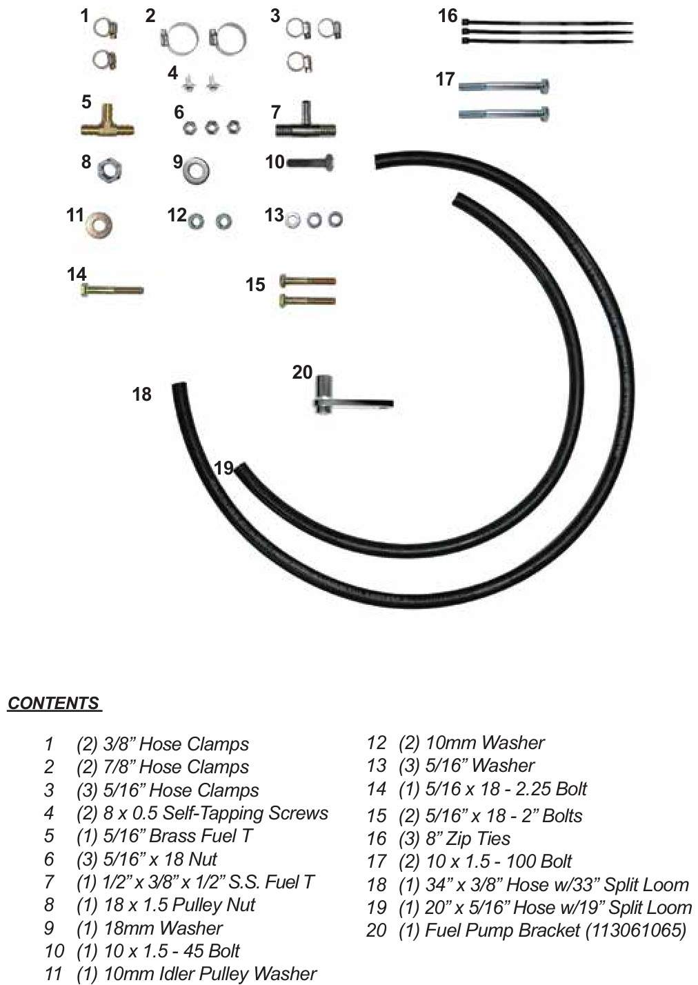
Box 1 Contents
- (2) 3/8″ Hose Clamps — item 1
- (2) 7/8″ Hose Clamps — item 2
- (3) 5/16″ Hose Clamps — item 3
- (2) 8 x 0.5 Self-Tapping Screws — item 4
- (1) 5/16″ Brass Fuel T — item 5
- (3) 5/16″ x 18 Nut — item 6
- (1) 1/2″ x 3/8″ x 1/2″ S.S. Fuel T — item 7
- (1) 18 x 1.5 Pulley Nut — item 8
- (1) 18 mm Washer — item 9
- (1) 10 x 1.5 - 45 Bolt — item 10
- (1) 10 mm Idler Pulley Washer — item 11
- (2) 10 mm Washer — item 12
- (3) 5/16″ Washer — item 13
- (1) 5/16 x 18 - 2.25 Bolt — item 14
- (2) 5/16″ x 18 - 2″ Bolts — item 15
- (3) 8″ Zip Ties — item 16
- (2) 10 x 1.5 - 100 Bolt — item 17
- (1) 34″ x 3/8″ Hose w/ 33″ Split Loom — item 18
- (1) 20″ x 5/16″ Hose w/ 19″ Split Loom — item 19
- (1) Fuel Pump Bracket (113061065) — item 20
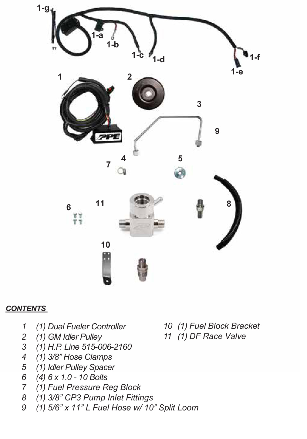
Box 2 Contents
- (1) Dual Fueler Controller — item 1 (sub-items 1-a through 1-g)
- (1) GM Idler Pulley — item 2
- (1) H.P. Line 515-006-2160 — item 3
- (1) 3/8″ Hose Clamp — item 4
- (1) Idler Pulley Spacer — item 5
- (4) 6 x 1.0 - 10 Bolts — item 6
- (1) Fuel Pressure Reg Block — item 7
- (1) 3/8″ CP3 Pump Inlet Fittings — item 8
- (1) 5/16″ x 11″ L Fuel Hose w/ 10″ Split Loom — item 9
- (1) Fuel Block Bracket — item 10
- (1) DF Race Valve — item 11
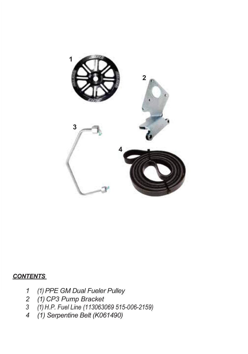
Box 3 Contents
- (1) PPE GM Dual Fueler Pulley — item 1
- (1) CP3 Pump Bracket — item 2
- (1) H.P. Fuel Line (113063069 / 515-006-2159) — item 3
- (1) Serpentine Belt (K061490) — item 4
Torque Specifications
- Idler pulley (#2) to engine bracket: 27 lb-ft
- Dual Fueler bracket assembly to A/C compressor (#17 bolts): 37 lb-ft
- DF Race Valve (#11) into fuel rail: 72–75 lb-ft
- High-pressure line (#4) nuts — all four ends: 30 lb-ft
Preparation
- Disconnect both batteries.
- Remove the factory air box and intake tube. Disconnect the electrical connectors.
- Remove the upper plastic fan shroud.
- Remove the fan blade and fan clutch.
- After removing the fan, remove the belt from all of the pulleys.
- If the vehicle was equipped with dual alternators, remove the second alternator — it will not be reused. Wrap the wires in electrical tape.
- Remove the bottom idler pulley.
- Remove both right-side A/C bolts.
Installation
Mount the Idler Pulley and Dual Fueler Pump Bracket
First, install the “Dual Fueler” bracket and pulley onto the pump if not already assembled.
- With the belt removed, install the #2 Idler Pulley in the existing threaded hole on the engine bracket as shown (Fig. 1). Torque to 27 lb-ft.
- Remove the 4 A/C bolts as shown and set the A/C compressor to the left of the engine to access the fuel line below (Fig. 2).
- Locate the stock CP3 pump (C) and the stock return line (D) from the stock CP3 pump. Cut the rubber hose and insert the #5 5/16″ x 5/16″ x 5/16″ ‘T’ connector. Use #3 hose clamps to secure.
- Plug the wire harness (E) into the #1 Control Module plug, then plug the other end of the #1 Control Module plug back into the stock CP3 pump (C).
- Place the A/C compressor back into its original position. Place the #2 Dual Fueler assembly (bracket with pump) on top of the right A/C compressor bolt holes and use the #17 bolts to attach the Dual Fueler bracket assembly to the A/C compressor. Torque to 37 lb-ft. Save 1 original A/C bolt for the next step.

Route the Dual Fueler Intake (Supply) Line
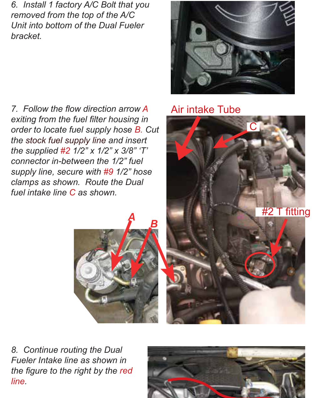
- Install 1 factory A/C bolt (the one you removed from the top of the A/C unit) into the bottom of the Dual Fueler bracket.
- Locate the fuel supply hose (B). Cut the stock fuel supply line and insert the supplied #2 1/2″ x 1/2″ x 3/8″ ‘T’ connector in-between the 1/2″ fuel supply line; secure with #9 1/2″ hose clamps as shown. Route the Dual Fueler intake line (C) as shown.
- Continue routing the Dual Fueler intake line as shown by the red line in the figure.
Install the DF Race Valve and High-Pressure Line
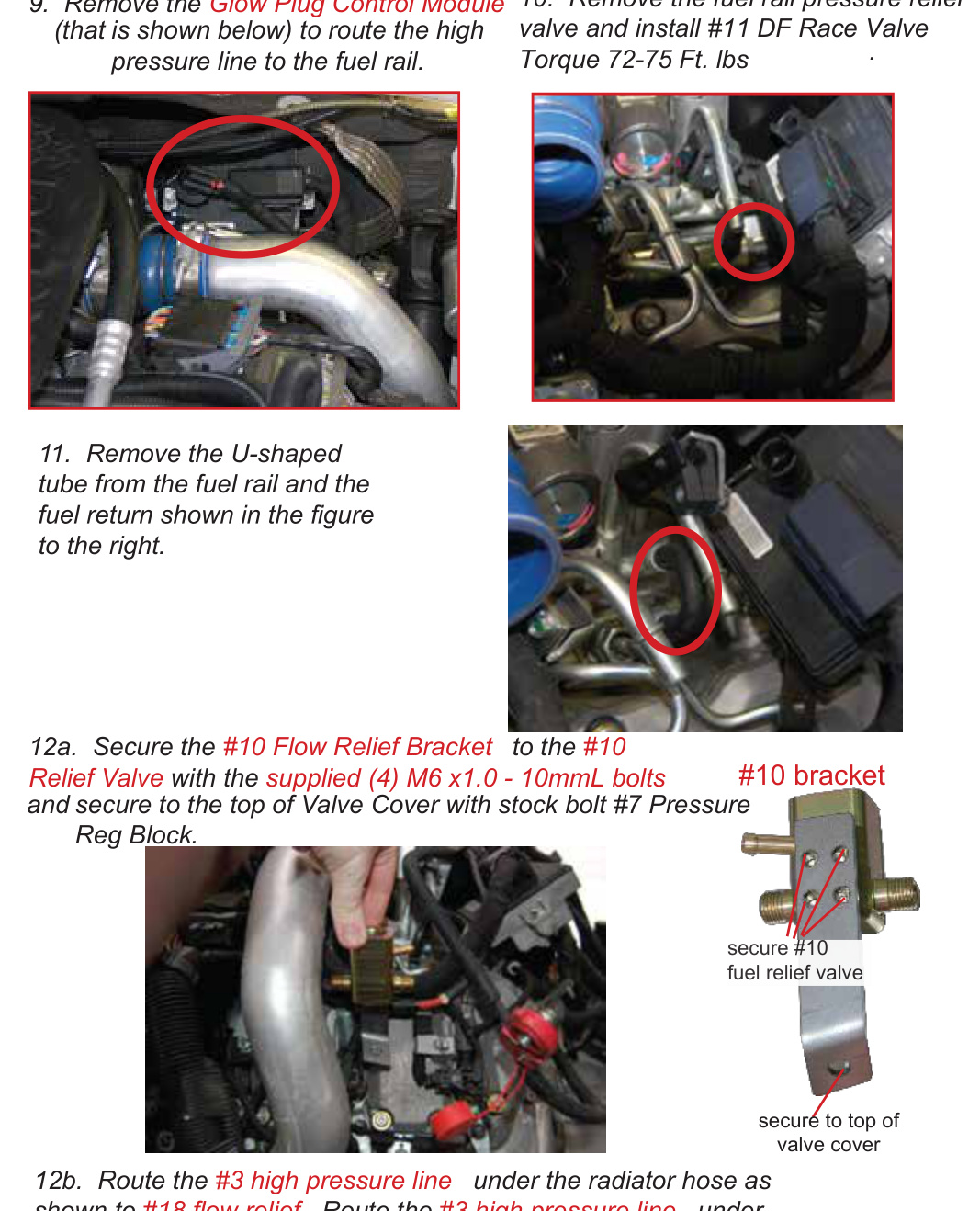
- Remove the Glow Plug Control Module (shown in the figure) to route the high-pressure line to the fuel rail.
- Remove the fuel rail pressure relief valve and install the #11 DF Race Valve. Torque to 72–75 lb-ft.
- Remove the U-shaped tube from the fuel rail and set it aside (to the right).
-
Secure the high-pressure line and flow relief bracket:
- Secure the #10 Flow Relief Bracket to the #10 Relief Valve with the supplied (4) M6 x 1.0 - 10 mm bolts, and secure it to the top of the valve cover with the stock bolt (#7 Pressure Reg Block).
- Route the #3 high-pressure line under the radiator hose as shown, then under the removed glow plug control module to the fuel rail and install it. Torque the #4 high-pressure line nut on all 4 ends to 30 lb-ft.
Connect the Fuel Lines and Return
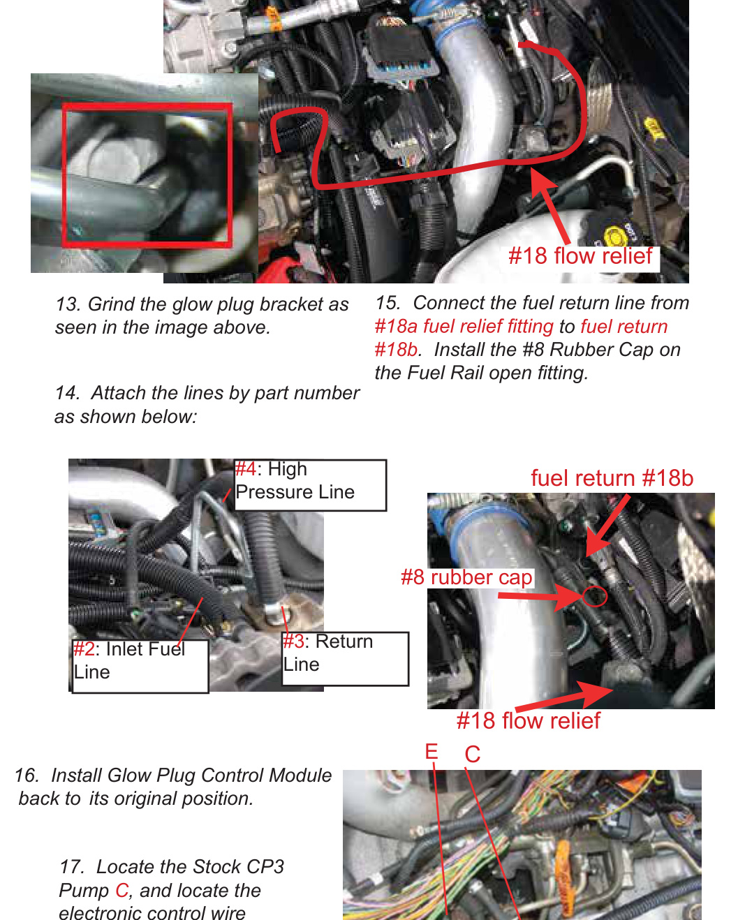
- Grind the glow plug bracket as seen in the figure.
- Attach the lines by part number as shown: #4 High Pressure Line, #2 Inlet Fuel Line, and the return line.
- Connect the fuel return line to fuel return #18b. Install the #8 rubber cap on fuel return #18b.
- Locate the stock CP3 pump (C) and the electronic control wire harness (E). Unplug the harness (E).
- Install the Glow Plug Control Module back into its original position.
Controller Wiring and Belt
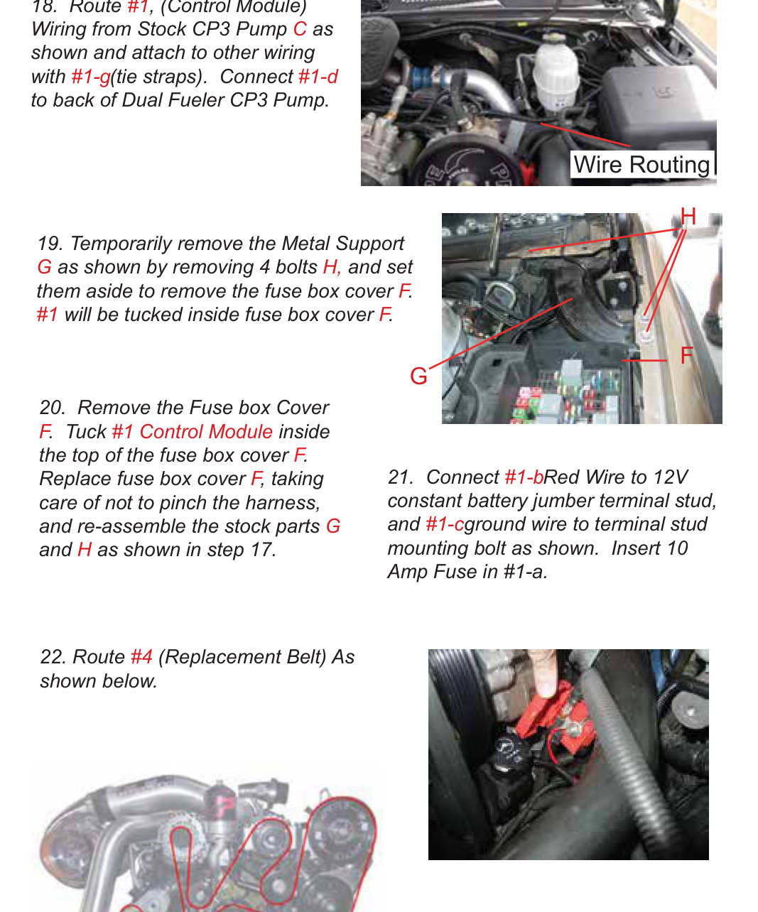
- Route the #1 Control Module wiring from the stock CP3 pump (C) as shown and attach it to the other wiring with the #1-g tie straps. Connect #1-d to the back of the Dual Fueler CP3 pump.
- Temporarily remove the metal support (G) by removing the 4 bolts (H) and set them aside, in order to remove the fuse box cover (F). The #1 controller will be tucked inside the fuse box cover (F).
- Remove the fuse box cover (F). Tuck the #1 Control Module inside the top of the fuse box cover. Replace the fuse box cover, taking care not to pinch the harness, and re-assemble the stock parts (G and H).
- Connect the #1-b red wire to the 12 V constant battery jumper terminal stud, and the #1-c ground wire to the terminal stud mounting bolt as shown. Insert the 10 amp fuse into #1-a.
- Route the #4 replacement serpentine belt as shown.
- Prime the fuel pump to bleed air from the system, then start the engine.
IMPORTANT: Prime the fuel pump and bleed all air from the system before starting the engine. After starting, inspect every fuel connection for leaks and confirm the new serpentine belt is seated correctly on all pulleys.
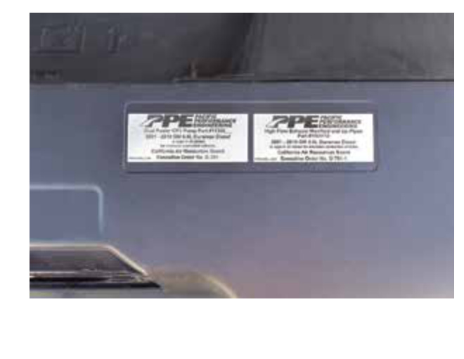
Final Step — Smog Certification Decal
- Place the supplied Dual Fueler decal on the engine shield in the designated area for use during future smog testing.