
Installation guide for the PPE Dual Fueler CP3 pump kit for LBZ/LMM Duramax trucks. Adding a second CP3 injection pump supplies the extra fuel volume needed for high-horsepower builds. This guide covers the supplied parts, belt and idler setup, and high-pressure fuel-line routing.
Download the Original PDF Manual
50-state emissions legal. For technical support, call PPE at (714) 985-4825.
IMPORTANT: This is a performance product that increases horsepower above factory specifications. Additional horsepower creates more stress on the drivetrain components, which could result in drivetrain failure. Installation should only be performed by someone knowledgeable in the repair and modification of high-pressure diesel fuel systems.
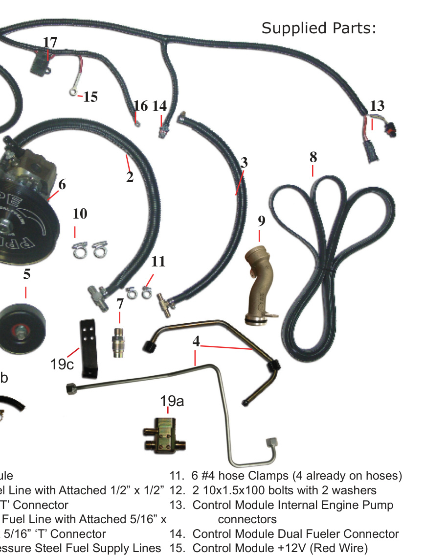
Supplied Parts
Note these part numbers — they are referenced throughout the installation steps below.
- 1. Control Module
- 2. 3/8″ inlet fuel line with attached 1/2″ x 1/2″ x 3/8″ ‘T’ connector
- 3. 5/16″ return fuel line with attached 5/16″ x 5/16″ x 5/16″ ‘T’ connector
- 4a, 4b. High-pressure steel fuel supply lines
- 5. Idler pulley with attached parts
- 6. Assembled CP3 pump, wheel and bracket
- 7. Dual Fueler race valve (fuel rail fitting)
- 8. #6 rib belt
- 9. Oil fill tube
- 10. 2 × #6 hose clamps
- 11. 6 × #4 hose clamps (4 already on hoses)
- 12. 2 × 10×1.5×100 bolts with 2 washers
- 13. Control module internal engine pump connectors
- 14. Control module Dual Fueler connector
- 15. Control module +12V (red wire)
- 16. Control module ground (black wire)
- 17. Control module 10A fuse
- 18. Control module harness tie straps
- 19a, 19b, 19c. Flow relief valve with fuel return line & clamps, and flow relief valve bracket
Torque Specifications
- Idler pulley (#5) to engine bracket — 27 ft-lbs
- Dual Fueler bracket assembly to A/C compressor (#12 bolts) — 37 ft-lbs
- High-pressure line (#4) nuts, all 4 ends — 30 ft-lbs
Installation
1. Mount the Idler Pulley and Dual Fueler Pump
First, install the “Dual Fueler” bracket and pulley onto the pump if they are not already assembled.
- Remove the belt and install the #5 idler pulley into the existing threaded hole on the engine bracket. Torque to 27 ft-lbs.
- Remove the 4 A/C compressor bolts as shown and set the A/C compressor to the left of the engine to access the fuel line below.
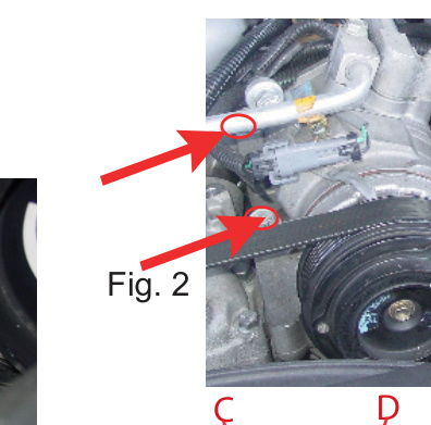
- Locate the stock CP3 pump (C) and its stock return line (D). Cut the rubber return hose and insert the #3 5/16″ x 5/16″ x 5/16″ ‘T’ connector. Secure with #11 hose clamps.
- Plug the wire harness (E) into the #13 control module plug, then plug the other end of the #13 control module plug back into the stock CP3 pump (C).
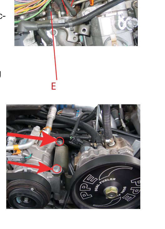
- Place the A/C compressor back into its original position. Set the #6 Dual Fueler assembly (bracket with pump) on top of the right A/C compressor bolt holes and use the #12 bolts to attach the Dual Fueler bracket assembly to the A/C compressor. Torque to 37 ft-lbs. Save one original A/C bolt for the next step.
2. Route the Inlet (Supply) Fuel Line
- Install one factory A/C bolt that you removed from the top of the A/C unit into the bottom of the Dual Fueler bracket.
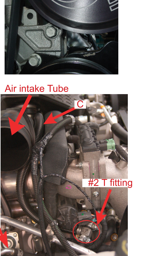
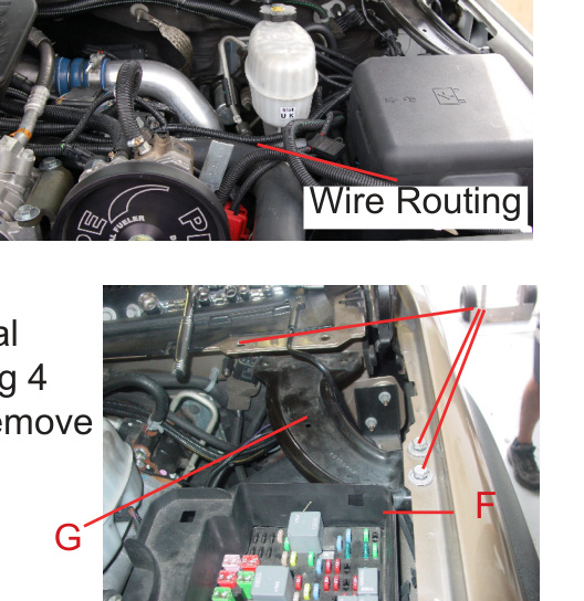
- Follow the flow-direction arrow (A) exiting the fuel filter housing to locate the fuel supply hose (B). Cut the stock 1/2″ fuel supply line and insert the supplied #2 1/2″ x 1/2″ x 3/8″ ‘T’ connector in-between the line. Secure with the #10 1/2″ hose clamps, then route the Dual Fueler intake line (C) as shown.
- Continue routing the Dual Fueler intake line up and over toward the air intake tube (follow the red path in the figure).
3. Install the High-Pressure Lines and Flow Relief Valve
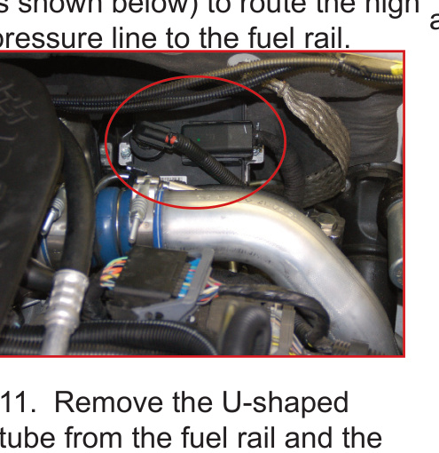
- Remove the module (M) shown below to allow the high-pressure line to be routed to the fuel rail.
- Remove the fuel rail plug and install the #7 fuel rail fitting.
- Remove the U-shaped tube from the fuel rail along with the fuel return.
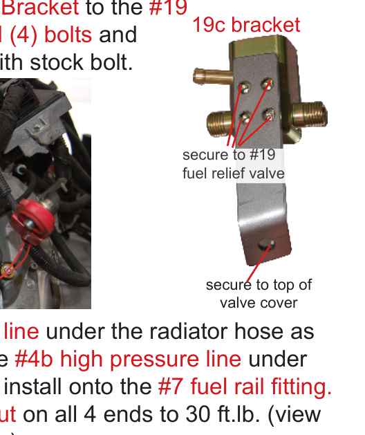
- 12a. Secure the #19c flow relief bracket to the #19 flow relief valve with the supplied (4) bolts, then secure the bracket to the top of the valve cover with a stock bolt.
- 12b. Route the #4a high-pressure line under the radiator hose to the #19 flow relief. Route the #4b high-pressure line under the removed module M to the fuel rail and install it onto the #7 fuel rail fitting. Torque the #4 high-pressure line nut on all 4 ends to 30 ft-lbs.
4. Connect the Fuel Lines and Return
- Grind the glow plug bracket as shown for clearance.
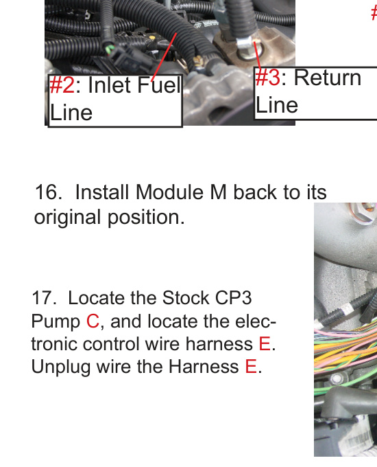
- Attach the lines by part number: #4 high-pressure line, #3 return line, and #2 inlet fuel line.
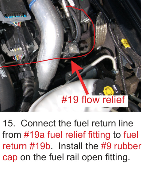
- Connect the fuel return line from the #19a fuel relief fitting to the fuel return #19b. Install the #9 rubber cap on the fuel rail’s open fitting.
- Install module M back into its original position.
- Locate the stock CP3 pump (C) and the electronic control wire harness (E). Unplug wire harness (E).
5. Route and Connect the Control Module Wiring
- Route the #1 control module wiring from the stock CP3 pump (C) as shown and bundle it to the other wiring with the #18 tie straps. Connect the #14 connector to the back of the Dual Fueler CP3 pump.
- Temporarily remove the metal support (G) by removing the 4 bolts (H), and set them aside so you can remove the fuse box cover (F). The #1 control module will be tucked inside the fuse box cover.
- Remove the fuse box cover (F). Tuck the #1 control module inside the top of the fuse box cover, then replace the cover — taking care not to pinch the harness — and reassemble the stock parts (G and H) as shown in Step 17.
- Connect the #15 red wire to the 12V constant battery jumper terminal stud, and the #16 ground wire to the terminal stud mounting bolt as shown. Insert the 10 amp fuse into #17.
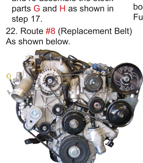
6. Install the Belt and Start the Engine
- Route the #8 replacement belt as shown in the diagram.
- The engine should now be ready to start. Prime the fuel filter pump to bleed air from the system, then start the engine.
WARNING: After starting the engine, check all fuel-line connections for leaks. If any leak is present, shut the engine off immediately and repair it before continuing.
7. Final Step
- Place the supplied Dual Fueler decal on the engine shield in the designated area for use during future smog testing.