Installation guide for the PPE Dual Fueler CP3 pump kit, part #113062000, for LLY Duramax trucks. Adding a second CP3 injection pump supplies the extra fuel volume needed for high-horsepower builds. This guide covers the supplied parts, dual idler pulleys and high-pressure fuel-line routing.
Download the Original PDF Manual
IMPORTANT: Please note the supplied part numbers below — they are referenced throughout the installation descriptions (for example, “#4 high pressure line” or “#20 mounting bracket”).
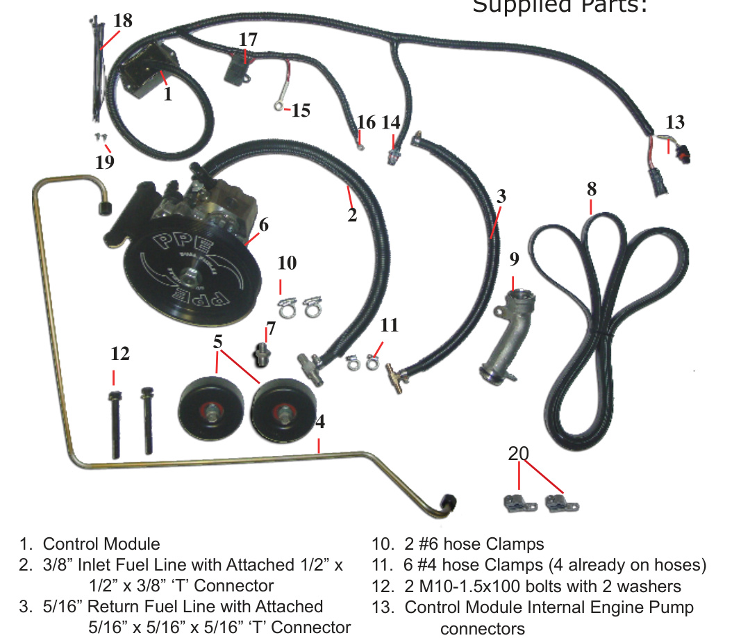
Supplied Parts
- Control Module
- 3/8″ Inlet Fuel Line with attached 1/2″ x 1/2″ x 3/8″ ‘T’ connector
- 5/16″ Return Fuel Line with attached 5/16″ x 5/16″ x 5/16″ ‘T’ connector
- High Pressure Steel Fuel Supply Line
- Two Idler Pulleys with bolts
- Assembled CP3 Pump, Wheel, and bracket
- Fuel Rail Fitting
- 6-Rib Belt
- Oil Filler Tube
- 2 #6 hose clamps
- 6 #4 hose clamps (4 already on hoses)
- 2 M10-1.5×100 bolts with 2 washers
- Control Module Internal Engine Pump connectors
- Control Module Dual Fueler connector
- Control Module +12V (Red Wire)
- Control Module Ground (Black Wire)
- Control Module Fuse 10A
- Control Module Harness Tie Straps
- Control Module Mounting Screws
- Two Fuel Supply Line Mounting Brackets
Tools & Torque Specifications
- 500E Torx wrench or socket (the type used on seatbelt bolts) — for the fuel rail plug
- #5 Idler Pulley (P1, engine bracket): 27 lb-ft
- #4 High pressure line nut, pump and fuel rail ends: 30 lb-ft
- #6 Dual Fueler bracket assembly to A/C compressor (#12 bolts): 37 lb-ft
- #9 Replacement oil filler tube: 15 lb-ft
- Fuel injection pump drive pulley nut (Appendix B): 52 lb-ft
NOTE: First, install the “Dual Fueler” bracket and the pulley if they are not already assembled on the pump. Refer to Appendix B below before starting the steps below.
Installation
Steps 1–6: Idler Pulleys, Drain & Fuel Rail Fitting
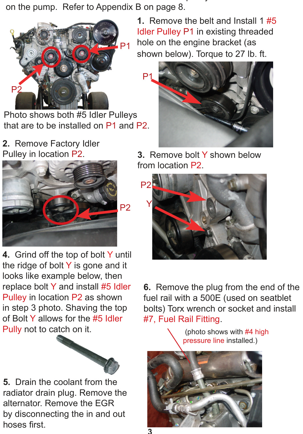
- Remove the belt and install one #5 Idler Pulley at location P1, in the existing threaded hole on the engine bracket (as shown below). Torque to 27 lb-ft.
- Remove the factory idler pulley in location P2.
- Remove bolt Y from location P2.
- Grind off the top of bolt Y until the ridge of the bolt is gone (see the example photo), then replace bolt Y and install the second #5 Idler Pulley in location P2. Shaving the top of bolt Y keeps the #5 idler pulley from catching on it.
- Drain the coolant from the radiator drain plug. Remove the alternator. Remove the EGR by disconnecting the in and out hoses first.
- Remove the plug from the end of the fuel rail with a 500E Torx wrench or socket, and install #7, the Fuel Rail Fitting.
Steps 7–11: High-Pressure Line, A/C Compressor & Pump Bracket
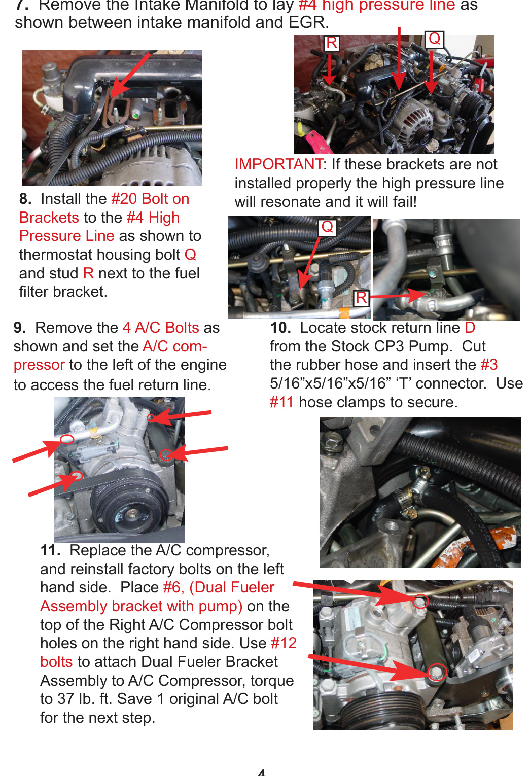
- Remove the intake manifold to lay the #4 high pressure line between the intake manifold and EGR (as shown).
- Install the #20 bolt-on brackets to the #4 high pressure line as shown — to thermostat housing bolt Q and to stud R next to the fuel filter bracket.
- Remove the 4 A/C bolts as shown, and set the A/C compressor to the left of the engine to access the fuel return line.
- Locate the stock return line D from the stock CP3 pump. Cut the rubber hose and insert the #3 5/16″×5/16″×5/16″ ‘T’ connector. Use #11 hose clamps to secure.
- Replace the A/C compressor and reinstall the factory bolts on the left-hand side. Place #6 (the Dual Fueler assembly bracket with pump) on top of the right A/C compressor bolt holes on the right-hand side. Use #12 bolts to attach the Dual Fueler bracket assembly to the A/C compressor; torque to 37 lb-ft. Save one original A/C bolt for the next step.
IMPORTANT: If the #20 brackets are not installed properly, the high pressure line will resonate and it will fail!
Steps 12–17: Fuel-Line Connections & Wire Harness
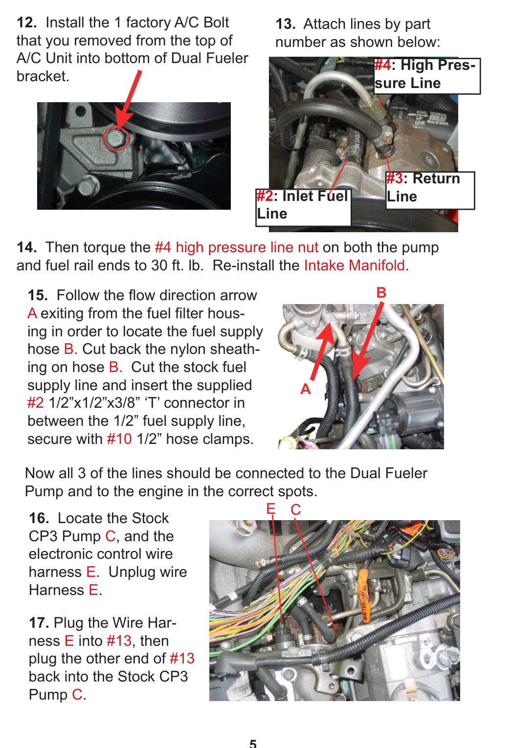
- Install the one factory A/C bolt that you removed from the top of the A/C unit into the bottom of the Dual Fueler bracket.
- Attach the lines by part number: #3 Return Line, #4 High Pressure Line, and #2 Inlet Fuel Line (as shown).
- Torque the #4 high pressure line nut on both the pump and fuel rail ends to 30 lb-ft. Re-install the intake manifold.
- Follow the flow-direction arrow A exiting from the fuel filter housing to locate fuel supply hose B. Cut back the nylon sheathing on hose B. Cut the stock fuel supply line and insert the supplied #2 1/2″×1/2″×3/8″ ‘T’ connector between the 1/2″ fuel supply line; secure with #10 1/2″ hose clamps.
- Locate the stock CP3 pump C and the electronic control wire harness E. Unplug wire harness E.
- Plug wire harness E into #13, then plug the other end of #13 back into the stock CP3 pump C.
NOTE: After Step 15, all three lines should be connected to the Dual Fueler pump and to the engine in the correct spots.
Steps 18–22: Control Module & Fuse Box
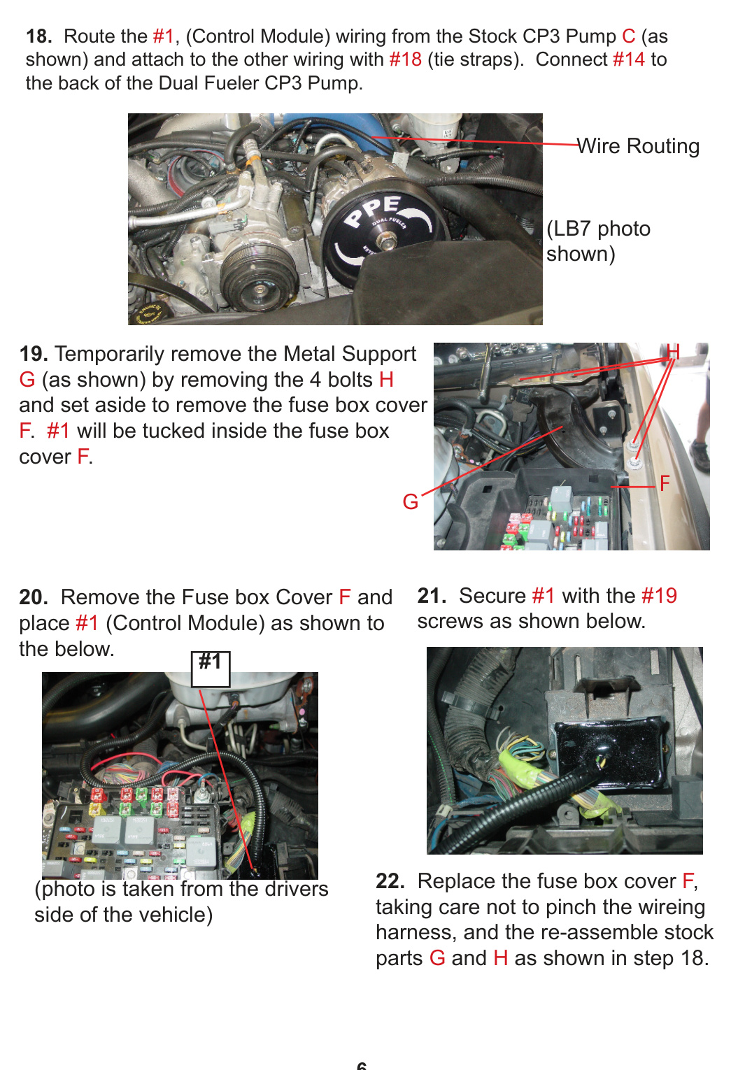
- Route the #1 Control Module wiring from the stock CP3 pump C (as shown) and attach it to the other wiring with #18 tie straps. Connect #14 to the back of the Dual Fueler CP3 pump.
- Temporarily remove the metal support G by removing the 4 bolts H, and set it aside to remove the fuse box cover F. The #1 Control Module will be tucked inside the fuse box cover F.
- Remove the fuse box cover F and place #1 (Control Module) as shown. (Photo is taken from the driver’s side of the vehicle.)
- Secure #1 with the #19 screws as shown.
- Replace the fuse box cover F, taking care not to pinch the wiring harness, then re-assemble stock parts G and H as shown in Step 18.
Steps 23–28: Oil Filler Tube, Belt, Power & Startup
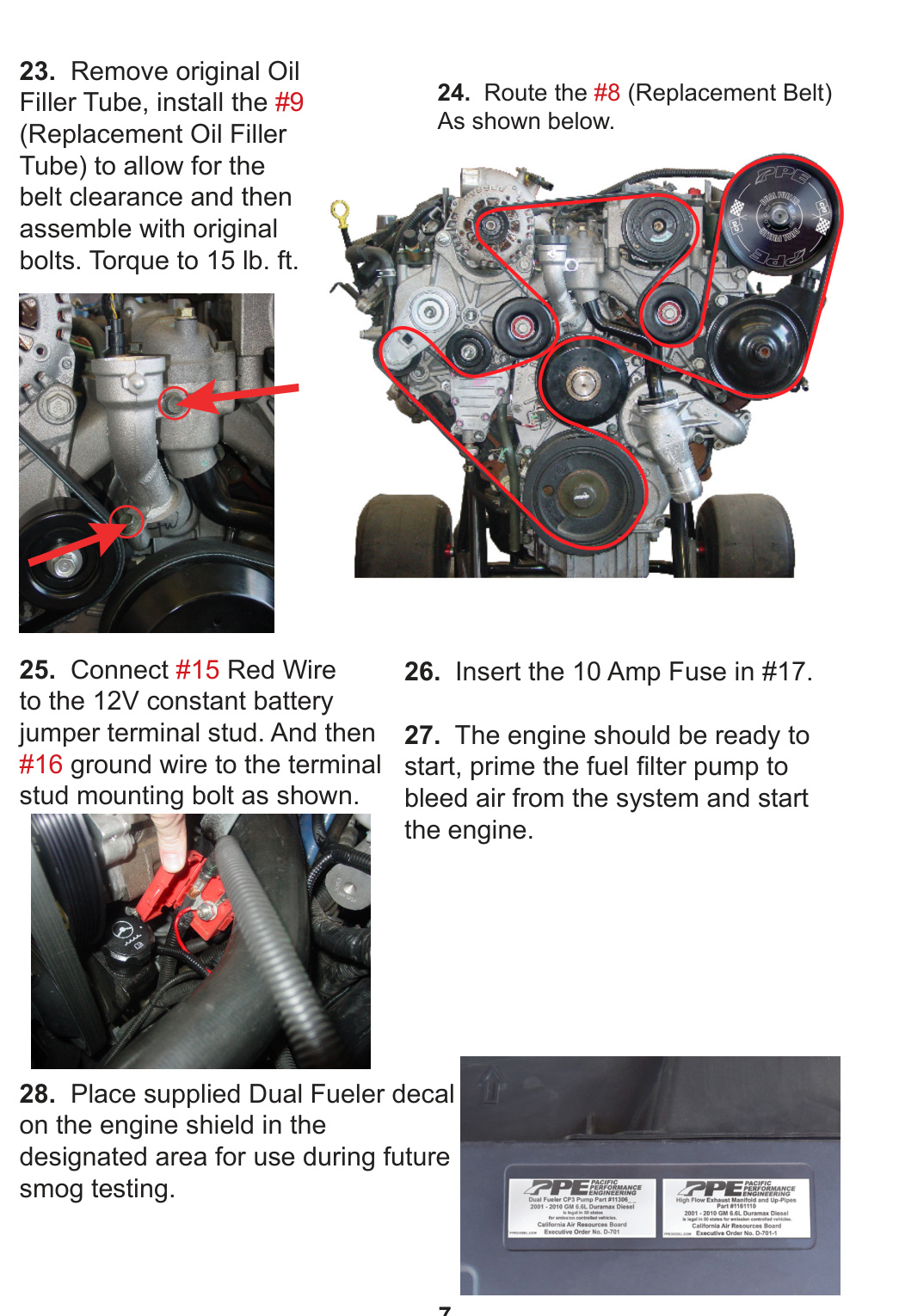
- Remove the original oil filler tube and install the #9 replacement oil filler tube to allow for belt clearance, then assemble with the original bolts. Torque to 15 lb-ft.
- Route the #8 replacement belt as shown.
- Connect the #15 red wire to the 12V constant battery jumper terminal stud, then connect the #16 ground wire to the terminal stud mounting bolt as shown.
- Insert the 10 Amp fuse in #17.
- The engine should now be ready to start. Prime the fuel filter pump to bleed air from the system, then start the engine.
- Place the supplied Dual Fueler decal on the engine shield in the designated area for use during future smog testing.
Appendix A: Troubleshooting
- Engine noisy / too much fuel pressure: Check that the fuse is good and seated in the controller’s fuse holder, and that all power connections are secure — including that both pump connectors are fully plugged in.
Appendix B: Fuel Pump with Bracket Assembly
If the bracket and pulley are not already assembled on the pump, complete this assembly first.
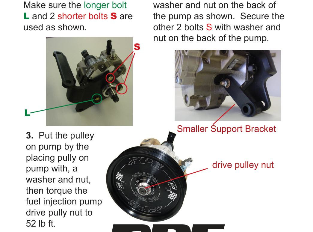
- Install the main bracket and insert the 3 supplied bolts. Make sure the longer bolt L and the 2 shorter bolts S are used as shown.
- Install the smaller support bracket and secure it with a washer and nut on the back of the pump as shown. Secure the other 2 bolts S with a washer and nut on the back of the pump.
- Put the pulley on the pump by placing it on the pump with a washer and nut, then torque the fuel injection pump drive pulley nut to 52 lb-ft.