
Installation guide for the PPE valve body recalibration (VBR) kit, part #128043000, for the Allison 1000 series (LLY/LBZ/LMM) behind 2001-2010 GM 6.6L Duramax engines. The VBR kit installs from the bottom—no transmission removal—and corrects shift complaints for short, crisp shifts.
Download the Original PDF Manual
Applications
- 2001–2010 GM 6.6L Duramax with Allison 1000 series transmission
- LLY / LBZ / LMM engine codes
What the VBR Kit Fixes
The valve body recalibration kit reduces or eliminates common driving complaints and delivers short, crisp, consistent shifts:
- Goes to neutral under high load
- Will not drive forward / backwards
- Sticks in one gear
- Sets trouble codes
IMPORTANT: Install the VBR kit before adding horsepower to help prevent internal transmission damage. The kit installs from the bottom of the transmission — no transmission removal is required.
Installation
Step 1 — Drain the Fluid
Drain the transmission fluid from the oil pan.
Step 2 — Remove the Oil Pan and Valve Body
- Remove the oil pan (12× 13 mm bolts).
- Remove the Valve Body (VB) from the transmission.
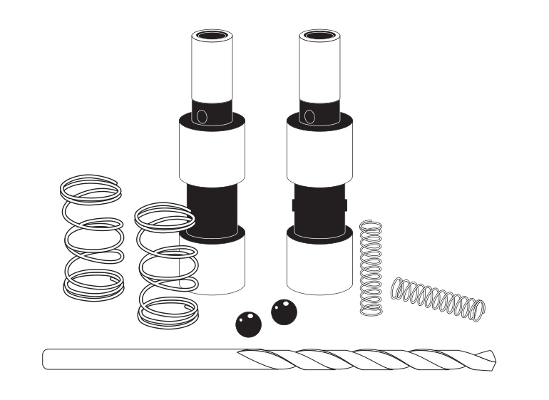
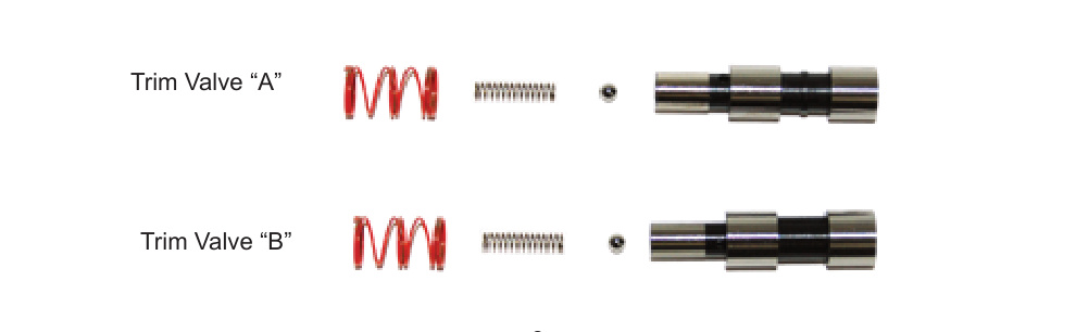
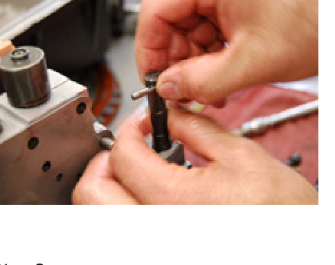
Step 3 — Replace the Trim Valves
- Discard the original Trim Valves and the springs on the small end.
- Insert the new balls and small springs into the small end of the new Trim Valves. Use TransJel or Vaseline to hold them in place.
- Place the new outer springs over the small end of the Trim Valves and install them into the Valve Body. Do not force them — a little “wiggling” and they will slide in.
- Install the outer spring on the “A” Solenoid Valve.
- Install the Solenoid Valves and Solenoids into the Valve Body.
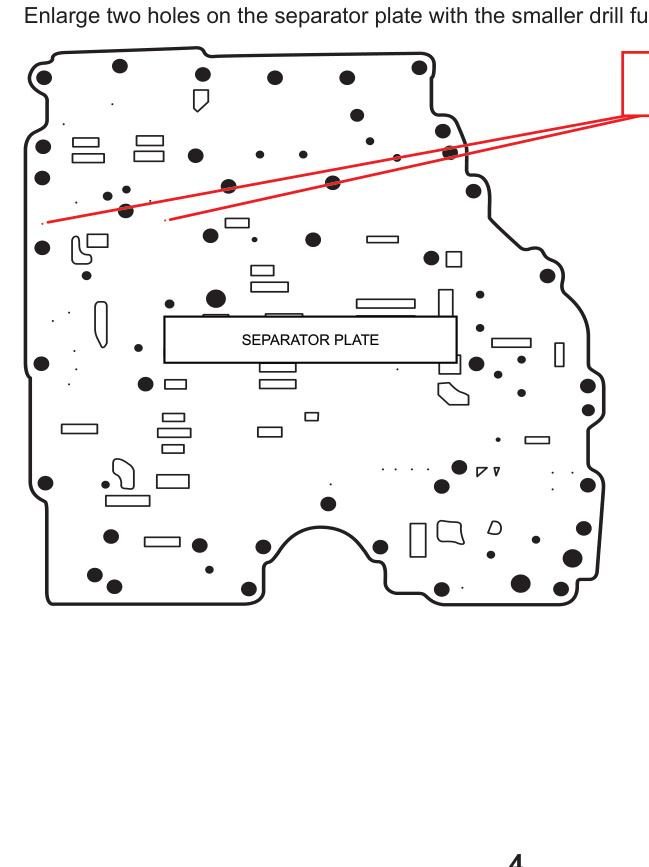
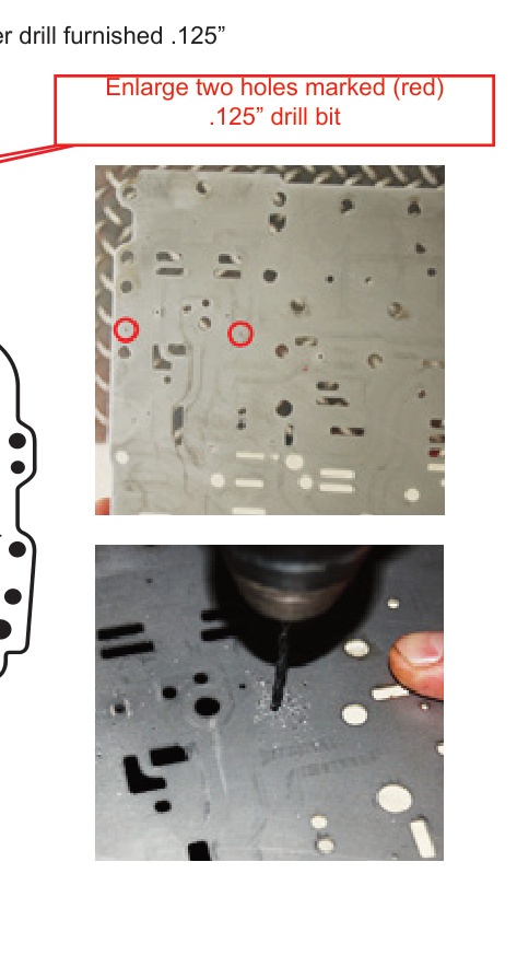
Step 4 — Enlarge the Separator Plate Holes
Enlarge the two marked holes on the separator plate using the smaller .125″ drill bit furnished in the kit.
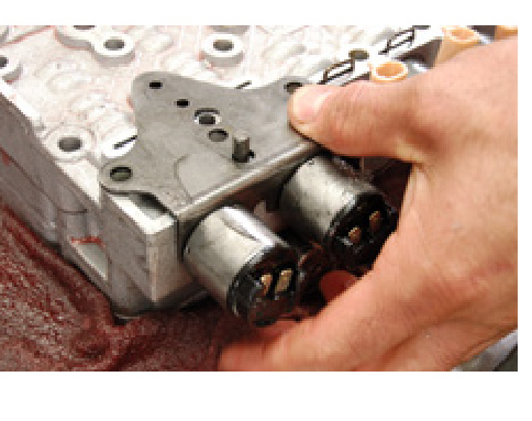
NOTE: Push the Solenoids firmly into the Valve Body when installing the Solenoid Bracket.
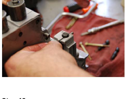
Step 5 — Install the Solenoid Bracket
Push the Solenoids firmly into the Valve Body while installing the Solenoid Bracket.
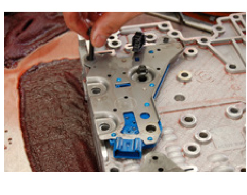
Step 6 — Pressure Switch O-Rings
The pressure switch installation must have six O-Rings.
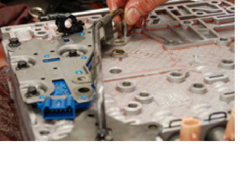
Step 7 — Set the Link
Place the link into the valve groove.
Step 8 — Slide in the Valve
Slide the valve into the Valve Body to hold the link in place.
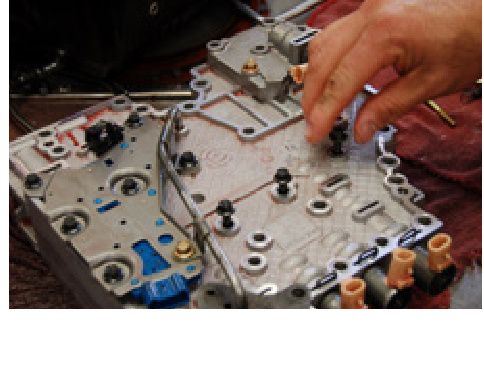
Step 9 — Install the Tube
Install the tube after the Accumulators and Solenoid Brackets (1× long gold bolt).
Step 10 — Reassemble
Install all bolts back into their original locations and complete the assembly by installing the Valve Body back into the transmission case.
Step 11 — Refill with Fluid
IMPORTANT: Do not start the engine unless the transmission has been filled with transmission oil — minimum 16 quarts with a shallow pan, 18 quarts with a heavy-duty deep pan (such as a PPE aluminum pan).
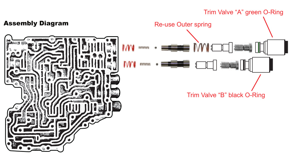
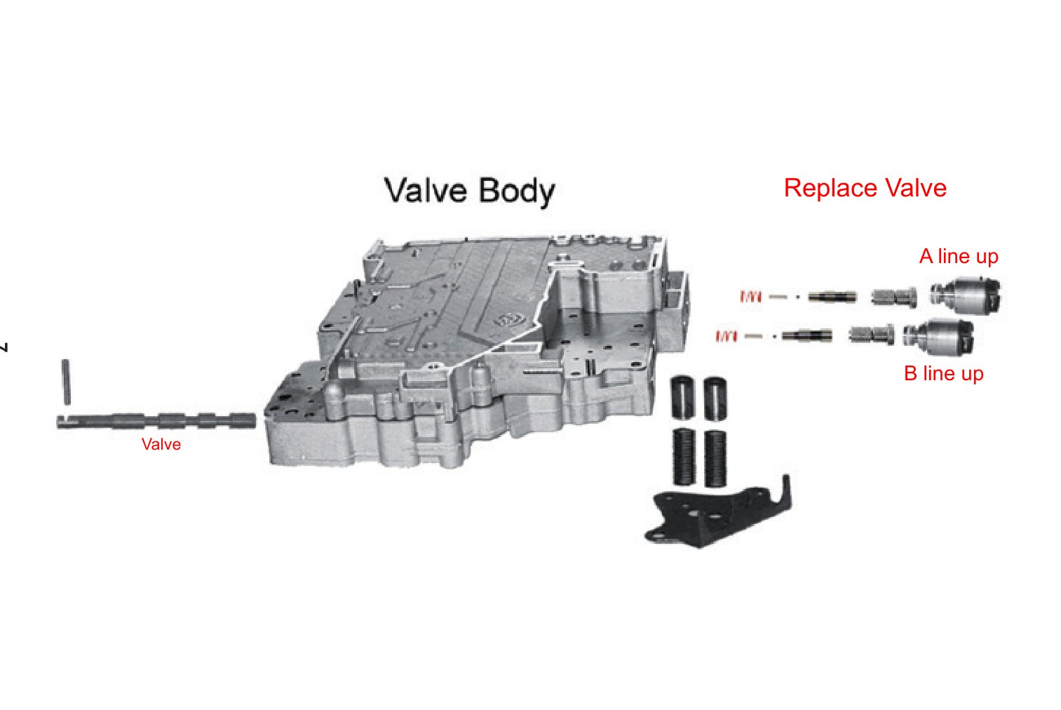
Valve Body Reference
Use the diagram below to confirm valve and solenoid orientation. Note the “A line up” and “B line up” positions when replacing the valves.
Transmission Relearn
IMPORTANT: A relearn is required after installing the PPE VBR kit, and any time you add horsepower or service the pump, valve body or clutches. The Allison 1000 uses an adaptive strategy that constantly adjusts shift clutch pressures to match engine torque and vehicle load, so it must re-learn after the change.
To perform the relearn:
- Make at least 6 sets of light-throttle upshifts through all gears.
- Make six sets of shifts at 1/3 throttle, then 1/2 throttle, then 3/4 throttle, and so on.
- Treat downshifts the same way — start with light throttle and work up to full throttle.
- When the shifts are quick and smooth, press the Tow/Haul button and start the relearn over.
NOTE: During the relearn, expect some clunks, bumps and shift flares — especially during the 3-4 shift. Bumps and flares are normal during the relearn.
The relearn takes about 2 hours. This can be greatly reduced by using PPE’s Xcelerator tuner and performing its Fast Re-learn feature.
Why the Relearn Matters
The truck’s computer continuously watches and records how the transmission behaves — for example, how long each gear change takes under various conditions. It calculates engine torque from inputs such as fuel consumption, boost pressure, air density, temperature and throttle position, then uses that data to estimate the load being accelerated and to calculate the optimum gear-change apply rate.
A perfect shift is as short in time as possible with minimum feel and stress on the drivetrain. For every gear change the system must release one gear and bring on the next. If the release and apply timing is wrong for a given torque and load, slipping or bind-up (two gears at the same time) can occur — both of which can cause major damage, including clutch failure. Allowing a full relearn lets the computer re-optimize this timing for the recalibrated valve body.