
Installation and adjustment notes for the South Bend dual disc clutch. Includes important Borg & Beck release-lever guidance: once the clutch is bolted to the flywheel, never pull the release lever away from the flywheel against the anti-rattle spring, as this can drop the strut out of position.
Download the Original PDF Manual
Important Safety Precautions
CAUTION: Do not lift this unit by the levers — damage can occur. All stamped edges are sharp and could cause injury. Wear appropriate gloves and eye protection when handling the clutch.
Borg & Beck Release-Lever Guidance
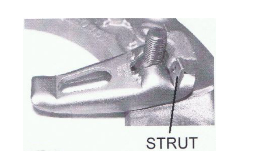
After the clutch is bolted to the flywheel, under no circumstance should the release lever (or the release-lever plate, if equipped) be pulled away from the flywheel against the anti-rattle spring pressure. Doing so will leave the strut in a “free” position and allow it to drop out of position.
A displaced strut can be identified by one or more release levers sitting higher than the others. This is the primary cause of strut displacement, and its importance cannot be over-stressed. If these circumstances occur, please contact South Bend Clutch as soon as possible.
Torque Specifications
- Flywheel to crank: 90–100 ft-lbs
- Pressure plate to flywheel: 45 ft-lbs
- Shift tower bolts to isolator plate / transmission case: 10.2–11.25 Nm (7.5–8.3 ft-lbs)
Clutch Installation Instructions
- Unbolt the pressure plate from the flywheel in a star pattern, using quarter turns.
- Check the discs on the input shaft for free movement before installation.
- Bolt the flywheel to the crank using the torque specs above.
- Line up the paint marks on the pressure plate, center plate, and flywheel.
- Install the discs according to the sticker (located on the disc) for the correct hub direction.
- Install the pressure-plate bolts in a crossing pattern, one quarter turn at a time.
IMPORTANT: Do not use air-powered tools for this step.
- Refer to the included Important Information Form for additional installation information.
Transmission Removal
- Disconnect the battery negative cable.
- Shift the transmission into Neutral.
- Remove the screws attaching the shift boot to the floor pan, then slide the boot upward on the shift lever.
- Remove the bolts holding the shift tower to the isolator plate and transmission gear case.
- Remove the shift tower and isolator plate from the transmission gear case.
- Raise and support the vehicle.
- Mark the propeller shaft and axle yokes for alignment reference. Use paint, a scriber, or chalk to mark the yokes.
- Remove the universal-joint strap screws and remove the straps.
- Remove the propeller shaft.
- Disconnect and remove the exhaust system as necessary.
- Disconnect the wires at the backup-light switch.
- Support the engine with an adjustable safety stand and wood block.
- If the transmission is to be disassembled for repair, remove the drain bolt at the bottom of the PTO cover and drain the lubricant from the transmission.
- Remove the bolts/nuts attaching the transmission to the rear mount.
- Support the transmission with a transmission jack and secure it with safety chains.
NOTE: It is recommended that a heavy-duty, scissors-style transmission jack be used to remove and install the NV5600 transmission.
- Remove the rear cross member.
- Remove the bolts attaching the clutch slave cylinder to the clutch housing, then move the cylinder aside for working clearance.
- Remove the wire harness from the clips on the transmission.
- Remove the bolts attaching the transmission clutch housing to the engine block.
- Slide the transmission and jack rearward until the input shaft clears the clutch disc and pressure plate.
- Lower the transmission jack and remove the transmission from under the vehicle.
Transmission Installation
Apply a light coat of MOPAR high-temperature bearing grease to the contact surfaces of the following components:
- Input shaft splines and pilot bearing hub
- Release bearing slide surface of the front retainer
- Pilot bearing
- Release bearing bore
- Release fork
- Release fork ball stud
- Propeller shaft slip yoke
- Apply sealer to the threads of the bottom PTO cover bolt and install the bolt in the case.
- Mount the transmission on the jack and position it under the vehicle.
NOTE: It is recommended that a heavy-duty, scissors-style transmission jack be used to remove and install the NV5600 transmission.
- Raise the transmission until the input shaft is centered in the clutch disc hub.
- Move the transmission forward and start the input shaft into the clutch disc and pilot bushing/bearing.
- Work the transmission forward until it is seated against the engine block. Do not allow the transmission to remain unsupported after the input shaft has entered the clutch disc.
- Install and tighten the transmission-to-engine-block bolts.
- Install the clutch slave cylinder.
- Connect the backup-light switch wires.
- Fill the transmission with the recommended lubricant. The correct fill level is the bottom edge of the fill-plug hole.
- Position the transmission harness wires in the clips on the transmission.
- Install the transmission mount on the transmission or rear cross member.
- Install the rear cross member.
- Remove the transmission jack and engine support fixture.
- Align and install the propeller shaft.
- Lower the vehicle.
- Shift the transmission into third gear.
- Clean the mating surfaces of the shift tower and isolator plate with a suitable wax and grease remover.
- Apply MOPAR Gasket Maker, or equivalent, to the sealing surface of the transmission case. Do not over-apply sealant.
- Install the isolator plate onto the transmission case, metal side down.
- Install the shift tower onto the isolator plate. No sealant is necessary between the shift tower and the top of the isolator plate.
- Verify that the shift tower, isolator plate, and shift socket are properly aligned.
- Install the bolts to hold the shift tower to the isolator plate and the transmission case. Tighten the shift tower bolts to 10.2–11.25 Nm (7.5–8.3 ft-lbs).
- Install the shift boot and bezel.
- Connect the battery negative cable.
Release Fork Orientation (Dodge Ram)
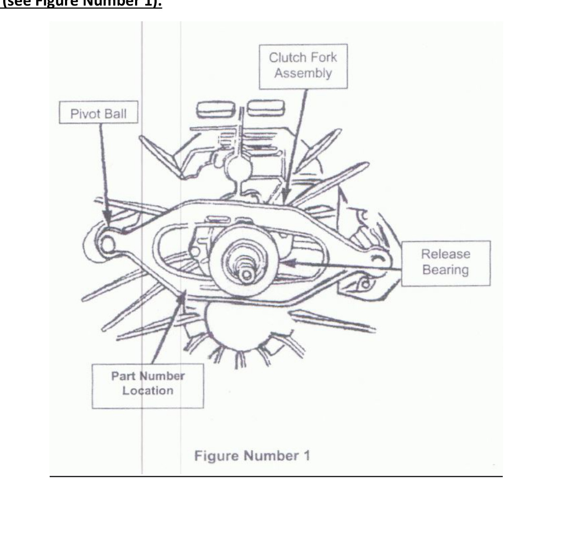
The clutch fork on this vehicle can be installed in the reverse position. When installed correctly, an incorrectly oriented fork results in a “growling” noise coming from the bell housing and/or a no-release condition. Refer to Figure 1 below for the correct fork orientation during assembly.
When the clutch fork is installed properly, the fork part number will be on the left side of the transmission input shaft. The left side of the transmission is the side where the pivot ball is located.
Prevent Your Clutch From Overheating
Feramic friction material, when heated to 1100°F, can run the risk of welding to the adjacent friction plates. Use the following steps to prevent this from happening:
- 3-second rule: Don’t slip your clutch for more than 3 seconds at high RPM.
- Don’t use the clutch to prevent rolling back on a hill.
- Engage the clutch as quickly as possible when taking off from a complete stop.
- Follow all break-in procedures.
What To Do When Your Clutch Gets Too Hot
Follow a few easy steps to lessen the damage if your clutch gets too hot:
- Hold the clutch pedal down for 10–15 seconds immediately after overheating to allow cooling time.
- Continue driving after overheating.
- If your clutch welds itself together, try starting the vehicle while in gear with your foot on the brake — this will many times break it free. (South Bend Clutch is not responsible for any damage.)
Applications
- 1994–2002 Dodge Ram — 8.0L V10 Gas
- 1994–2002 Dodge Ram — 5.9L Turbo Diesel