
Installation instructions for the South Bend Ford/Dodge 7.3L dual disc clutch kit (SDD/FDD). The guide lists flywheel-to-crank torque of 90-100 ft-lbs and pressure-plate torque of 45 ft-lbs, and walks through disc alignment and assembly for high clamp load and smooth engagement.
Download the Original PDF Manual
Torque Specifications
South Bend Ford/Dodge DD (7.3L)
- Flywheel to crank — 90–100 ft-lbs.
- Pressure plate to flywheel — 45 ft-lbs.
South Bend Ford 6.0 & 6.4 DD
- Flywheel to crank — 45–49 ft-lbs.
- Pressure plate to flywheel — 18–20 ft-lbs.
Clutch Assembly Instructions
The dual disc clutch is assembled to the flywheel using the same procedure for all listed applications. Follow the torque values for your specific kit from the section above.
- Unbolt the pressure plate from the flywheel in a star pattern, using quarter turns.
- Check the discs on the input shaft for free movement before installation.
- Bolt the flywheel to the crank using the provided torque specifications.
- Line up the paint marks on the pressure plate, center plate, and flywheel.
- Install the discs according to the sticker (located on the disc) for the correct hub direction.
- Install the pressure plate bolts in a crossing pattern, one quarter turn at a time.
IMPORTANT: Do not use air-powered tools when installing the pressure plate bolts. Refer to the Important Information Form (included with your kit) for additional installation information.
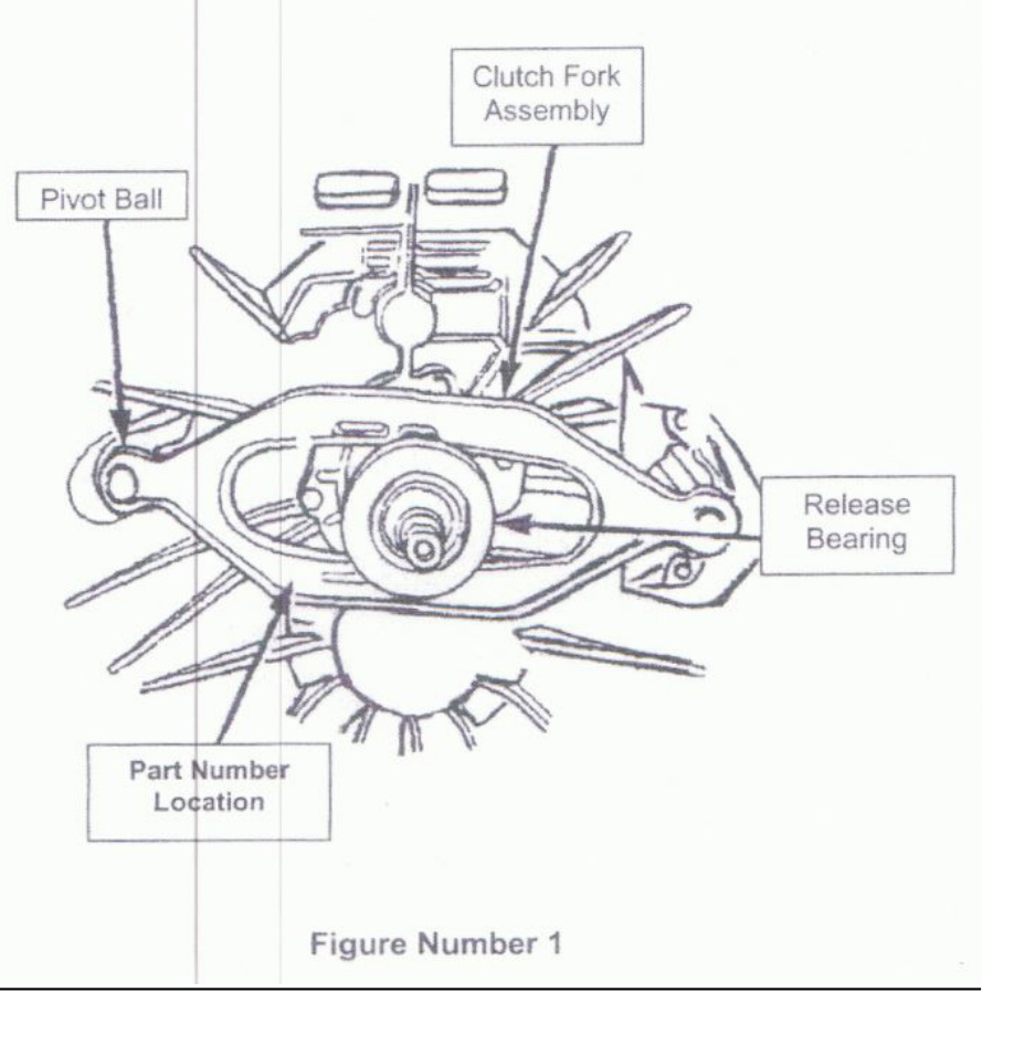
Release Fork Orientation (Dodge Ram Applications)
The clutch fork on these vehicles can be installed in the reverse position. When installed incorrectly, the result will be a “growling” noise coming from the bell housing and/or a no-release condition.
When the clutch fork is installed properly, the fork part number will be on the left side of the transmission input shaft. The left side of the transmission is the side where the pivot ball is located. Refer to the figure below for the correct fork orientation during assembly.
Applications
- 1994–2002 Dodge Ram — 8.0L V10 Gas
- 1994–2002 Dodge Ram — 5.9L Turbo Diesel
Important Information for SDD Clutches
South Bend Dual Disc clutches for Dodge & Ford diesel pick-up trucks.
This information is intended to help you understand what happens in your drive train when upgrades are introduced, and how some simple changes in driving habits can help.
When a gas engine runs, it has a smooth, uninterrupted rotation. A diesel engine is the opposite: it has a pulsation caused by small, quick spikes in torque (4–8 times per revolution, depending on the number of cylinders). This causes a vibration, most apparent at idle, which must be dampened so it is not transferred to the transmission and cause the gears to “clatter” and make noise.
When Dodge and Ford introduced the Dual Mass Flywheel (DMF), they successfully dampened this vibration. The DMF worked well when the engine ran at factory specifications and towing limits were not exceeded. As soon as these trucks began being used beyond OEM recommendations, problems started to occur. Horsepower and torque upgrades, excessive towing loads, and poor driving habits caused the DMF to wear out and eventually fail.
To handle these higher loads, South Bend developed a clutch system that can hold the extra torque while still providing a reasonable amount of dampening. To make a clutch withstand dramatic increases in torque and load, certain aspects of the system had to be strengthened — for example, the dampening springs in the clutch discs had to be stronger. The newer hub design reduces idle noise in most trucks without sacrificing torque capacity.
Keep in mind that noise is not always caused by the clutch. The way the engine runs and the amount of wear in the transmission (and usually a combination of both) directly affect the likelihood of noise at idle.
YOU MUST INSPECT THE TRANSMISSION. Late-model G-56 transmissions are prone to internal wear, especially the aluminum case. Have a qualified transmission specialist check the amount of play in your input shaft. Even a small amount of movement could indicate a problem that will worsen over time and could cause a catastrophic failure.
Driving Habits and Noise While Accelerating
Occasionally, customers report noise while accelerating, which often relates to driving habits. To conserve fuel, some drivers shift into the next gear too soon. If the transmission is in too high a gear at a low wheel speed, it causes a lugging effect on the engine. This lugging creates backlash in the splined hubs of the clutch discs and can cause unnecessary noise — most apparent in late-model, aluminum-cased transmissions.
NOTE: The solution is simple — keep the RPMs up while shifting. This will prolong the life of the entire drivetrain. With a stronger clutch system, you may need to adapt your driving style to suit the new components.
Transmission Removal
- Disconnect the battery negative cable.
- Shift the transmission into Neutral.
- Remove the screws attaching the shift boot to the floor pan, then slide the boot upward on the shift lever.
- Remove the bolts holding the shift tower to the isolator plate and transmission gear case.
- Remove the shift tower and isolator plate from the transmission gear case.
- Raise and support the vehicle.
- Mark the propeller shaft and axle yokes for alignment reference (use paint, scriber, or chalk).
- Remove the universal joint strap screws and remove the straps.
- Remove the propeller shaft.
- Disconnect and remove the exhaust system as necessary.
- Disconnect the wires at the backup light switch.
- Support the engine with an adjustable safety stand and wood block.
- If the transmission is to be disassembled for repair, remove the drain bolt at the bottom of the PTO cover and drain the lubricant from the transmission.
- Remove the bolts/nuts attaching the transmission to the rear mount.
- Support the transmission with a transmission jack and secure it with safety chains.
- Remove the rear cross member.
- Remove the bolts attaching the clutch slave cylinder to the clutch housing, then move the cylinder aside for working clearance.
- Remove the wire harness from the clips on the transmission.
- Remove the bolts attaching the transmission clutch housing to the engine block.
- Slide the transmission and jack rearward until the input shaft clears the clutch disc and pressure plate.
- Lower the transmission jack and remove the transmission from under the vehicle.
NOTE: It is recommended that a heavy-duty, scissors-style transmission jack be used to remove and install the NV5600 transmission.
Transmission Installation
Apply a light coat of MOPAR high-temperature bearing grease to the contact surfaces of the following components:
- Input shaft splines and pilot bearing hub
- Release bearing slide surface of the front retainer
- Pilot bearing
- Release bearing bore
- Release fork
- Release fork ball stud
- Propeller shaft slip yoke
- Apply sealer to the threads of the bottom PTO cover bolt and install the bolt in the case.
- Mount the transmission on the jack and position it under the vehicle.
- Raise the transmission until the input shaft is centered in the clutch disc hub.
- Move the transmission forward and start the input shaft in the clutch disc and pilot bushing/bearing.
- Work the transmission forward until it is seated against the engine block. Do not allow the transmission to remain unsupported after the input shaft has entered the clutch disc.
- Install and tighten the transmission-to-engine block bolts.
- Install the clutch slave cylinder.
- Connect the backup light switch wires.
- Fill the transmission with the recommended lubricant. The correct fill level is the bottom edge of the fill plug hole.
- Position the transmission harness wires in the clips on the transmission.
- Install the transmission mount on the transmission or rear cross member.
- Install the rear cross member.
- Remove the transmission jack and engine support fixture.
- Align and install the propeller shaft.
- Lower the vehicle.
- Shift the transmission into third gear.
- Clean the mating surfaces of the shift tower and isolator plate with a suitable wax and grease remover.
- Apply MOPAR Gasket Maker, or equivalent, to the sealing surface of the transmission case. Do not over-apply sealant.
- Install the isolator plate onto the transmission case, metal side down.
- Install the shift tower onto the isolator plate. No sealant is necessary between the shift tower and the top of the isolator plate.
- Verify that the shift tower, isolator plate, and shift socket are properly aligned.
- Install the bolts to hold the shift tower to the isolator plate and the transmission case. Tighten the shift tower bolts to 10.2–11.25 Nm (7.5–8.3 ft-lbs).
- Install the shift boot and bezel.
- Connect the battery negative cable.