
Installation guide for South Bend G56 clutch kits on Dodge Cummins 6-speed (G56) transmissions. All kits bolt to the bare crankshaft—remove any tin plate left on the crank flange after the OE flywheel comes off—and the correct crank spacer must be used with double disc clutches.
Download the Original PDF Manual
Important Message for All Dodge G56 Transmissions
- All of our clutch kits are made to be bolted to the bare crankshaft.
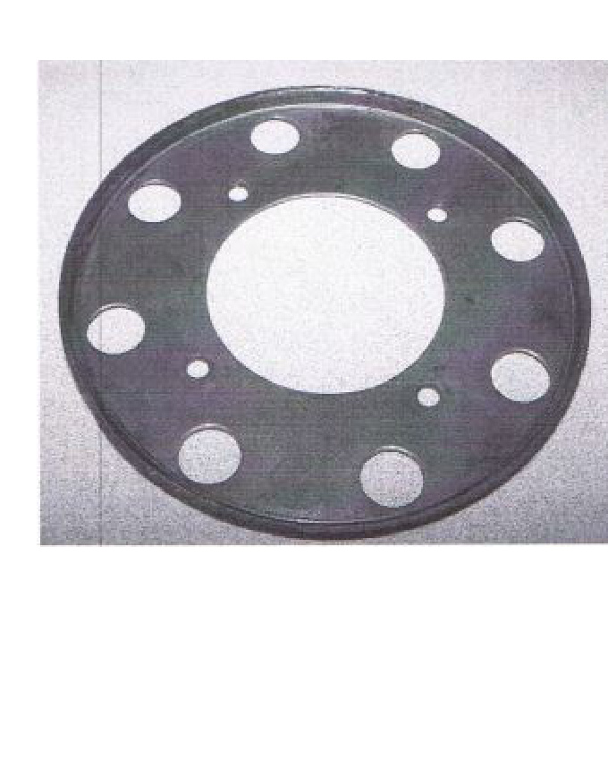
- In some cases, a tin plate (pictured below) may be on the crank flange after the O.E. flywheel is removed. This plate is NOT to be used with the replacement solid flywheel.
- When installing a competition double disc clutch, use the crank spacer provided.
- For the G56 ductile double disc (SDD), the crank spacer is built into the flywheel.
Dual Mass Flywheel Removal (2005.5–2008 Dodge Cummins G56)
ATTENTION: This procedure applies to 2005.5–2008 Dodge Cummins diesel G56 trucks equipped with a dual mass flywheel (DMF).
The DMF is bolted to a plate on the crank from the engine side. Access to the engine side of the plate can be found on the lower right side of the firewall. The flywheel must be rotated to remove all 8 bolts, then remove the plate from the crank.
Release Fork Orientation (Dodge Ram Applications)
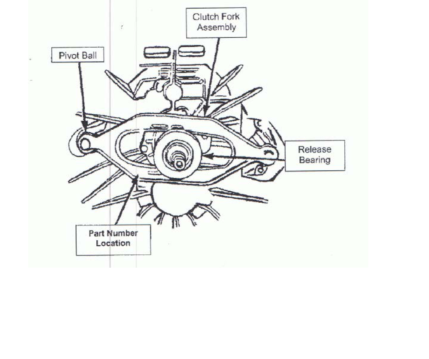
WARNING: The clutch fork on this vehicle can be installed in the reverse position. When installed incorrectly, the result will be a growling noise coming from the bell housing and/or a no-release condition. Refer to Figure 1 below for the correct fork orientation during assembly.
When the clutch fork is installed properly, the fork part number will be on the left side of the transmission input shaft. The left side of the transmission is the side where the pivot ball is located (see Figure 1).
Installation Instructions — Please Read Carefully
Never
- Force the input shaft into the disc hub — it will bend the disc or scar the splines.
- Allow the weight of the transmission to hang on the disc.
- Touch the friction surface of the disc with greasy hands.
- Use an impact wrench to tighten the pressure plate mounting bolts.
- Install a new disc without replacing the pressure plate and release bearing.
Always
- Use the proper alignment tool.
- Check the fit of the disc hub splines to the input shaft before installation.
- Resurface or replace the flywheel.
- Tighten the pressure plate bolts in a “star” or criss-cross pattern, one turn at a time.
WARNING: Failure to follow the above instructions will negatively affect the performance of your clutch and may void your warranty.
NOTE: This unit may appear different than your old part due to the design differences of various manufacturers. It will function properly in your vehicle. Some prying may be required to level the fingers of the clutch — use a small pry bar positioned between the cover and the diaphragm spring to force the high fingers down to a uniform position.
Bolt Torque Specifications
- Pressure plate to flywheel: 20 ft-lbs.
- Flywheel to crank (8 bolts): 95–105 ft-lbs (threadlock recommended).
- Shift tower bolts: 10.2–11.25 Nm (7.5–8.3 ft-lbs).
Flywheel Resurfacing
- Flywheels should NOT be lathe cut.
- The OEM taper on the flywheel runs approximately 0.002″–0.003″ from outside to inside. This does not need to be matched — flat is preferred with our clutch.
- Flywheels should be resurfaced with a grinder specifically built for grinding flywheels. Do not aim for a rough finish; the smoother the better.
- Make sure the pressure plate bolt holes are thoroughly cleaned after resurfacing. Running a thread chaser or tap will ensure the threads are clear of all debris.
Removal
- Disconnect the battery negative cable.
- Shift the transmission into Neutral.
- Remove the screws attaching the shift boot to the floor pan, then slide the boot upward on the shift lever.
- Remove the bolts holding the shift tower to the isolator plate and transmission gear case.
- Remove the shift tower and isolator plate from the transmission gear case.
- Raise and support the vehicle.
- Mark the propeller shaft and axle yokes for alignment reference. Use paint, a scriber, or chalk to mark the yokes.
- Remove the universal joint strap screws and remove the straps.
- Remove the propeller shaft.
- Disconnect and remove the exhaust system as necessary.
- Disconnect the wires at the backup light switch.
- Support the engine with an adjustable safety stand and wood block.
- If the transmission is to be disassembled for repair, remove the drain bolt at the bottom of the PTO cover and drain the lubricant from the transmission.
- Remove the bolts/nuts attaching the transmission to the rear mount.
- Support the transmission with a transmission jack. Secure the transmission to the jack with safety chains.
NOTE: It is recommended that a heavy-duty, scissors-style transmission jack be used to remove and install the transmission.
- Remove the rear cross member.
- Remove the bolts attaching the clutch slave cylinder to the clutch housing, then move the cylinder aside for working clearance.
- Remove the wire harness from the clips on the transmission.
- Remove the bolts attaching the transmission clutch housing to the engine block.
- Slide the transmission and jack rearward until the input shaft clears the clutch disc and pressure plate.
- Lower the transmission jack and remove the transmission from under the vehicle.
Installation
Apply a light coat of MOPAR high-temperature bearing grease to the contact surfaces of the following components:
- Input shaft splines and pilot bearing hub.
- Release bearing slide surface of the front retainer.
- Pilot bearing.
- Release bearing bore.
- Release fork.
- Release fork ball stud.
- Propeller shaft slip yoke.
- Apply sealer to the threads of the bottom PTO cover bolt and install the bolt in the case.
- Mount the transmission on the jack and position it under the vehicle.
NOTE: It is recommended that a heavy-duty, scissors-style transmission jack be used to remove and install the transmission.
- Raise the transmission until the input shaft is centered in the clutch disc hub.
- Move the transmission forward and start the input shaft in the clutch disc and pilot bushing/bearing.
- Work the transmission forward until it is seated against the engine block. Do not allow the transmission to remain unsupported after the input shaft has entered the clutch disc.
- Install and tighten the transmission-to-engine block bolts.
- Install the clutch slave cylinder.
- Connect the backup light switch wires.
- Fill the transmission with the recommended lubricant. The correct fill level is the bottom edge of the fill plug hole.
- Position the transmission harness wires in the clips on the transmission.
- Install the transmission mount on the transmission or rear cross member.
- Install the rear cross member.
- Remove the transmission jack and engine support fixture.
- Align and install the propeller shaft.
- Lower the vehicle.
- Shift the transmission into third gear.
- Clean the mating surfaces of the shift tower and isolator plate with a suitable wax and grease remover.
- Apply MOPAR Gasket Maker, or equivalent, to the sealing surface of the transmission case. Do not over-apply sealant.
- Install the isolator plate onto the transmission case, metal side down.
- Install the shift tower onto the isolator plate. No sealant is necessary between the shift tower and the top of the isolator plate.
- Verify that the shift tower, isolator plate, and shift socket are properly aligned.
- Install the bolts to hold the shift tower to the isolator plate and the transmission case. Tighten the shift tower bolts to 10.2–11.25 Nm (7.5–8.3 ft-lbs).
- Install the shift boot and bezel.
- Connect the battery negative cable.
Break-In
IMPORTANT: High-performance clutches require a break-in period. 200 miles of normal city driving (stop-and-go) should properly break in your clutch. If slipping occurs, resume normal driving for 50 miles.
Need Assistance?
- ECD Diesel: 717-861-7525
- South Bend Clutch (technical assistance): 800-988-4345