
Installation guide for the TS Performance MP-8 module for 1998-2005 Caterpillar C7 and 3126 and 2000-2007 C9 medium-duty engines (part #2110201 / #2110202 / #4111002). Confirm all listed contents are present, then follow the steps to install the MP-8 for added power.
Download the Original PDF Manual
This is a high-performance product intended for off-road use only. Use at your own risk.
Applications
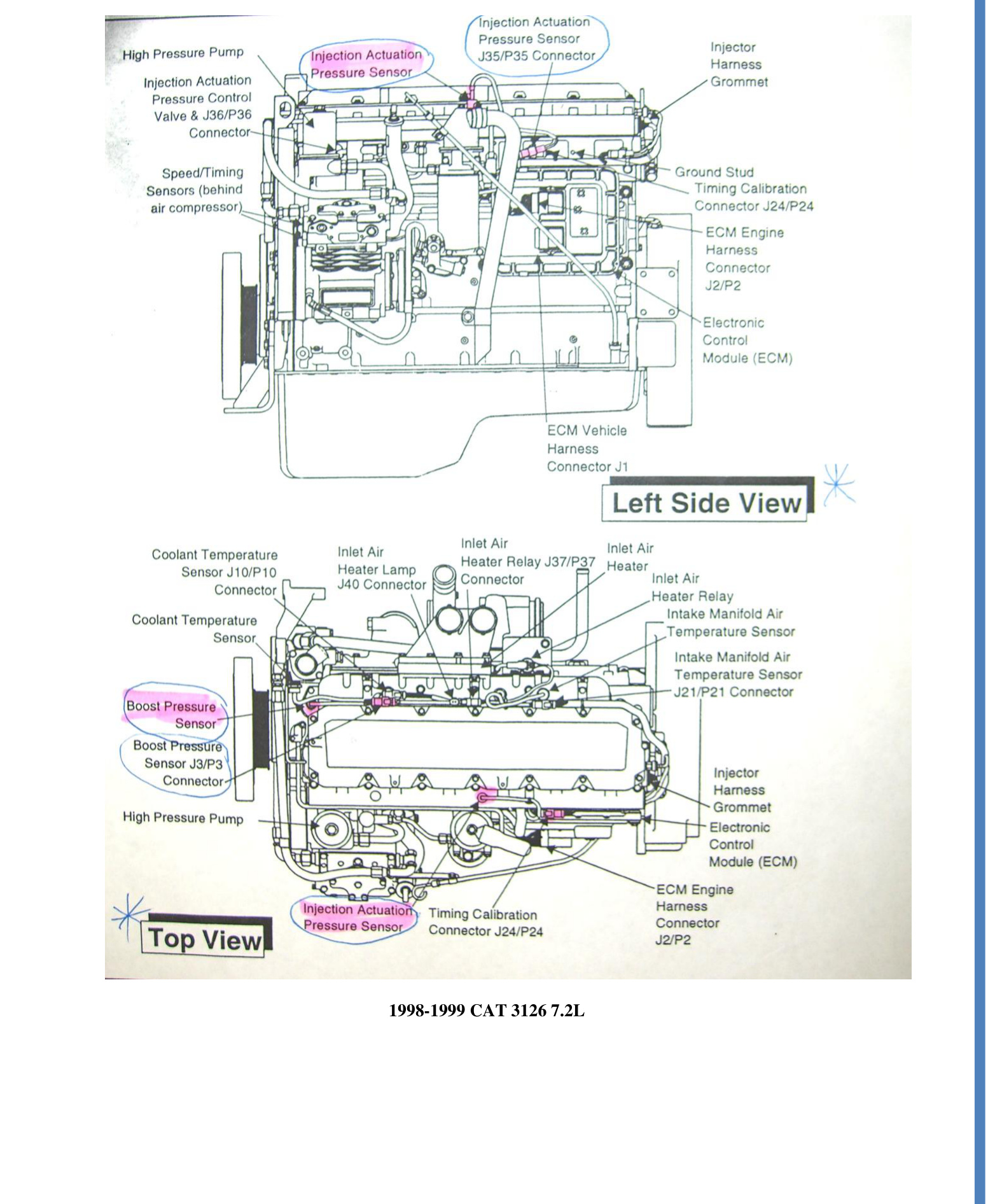
- 1998–1999 Cat 3126 (7.2L)
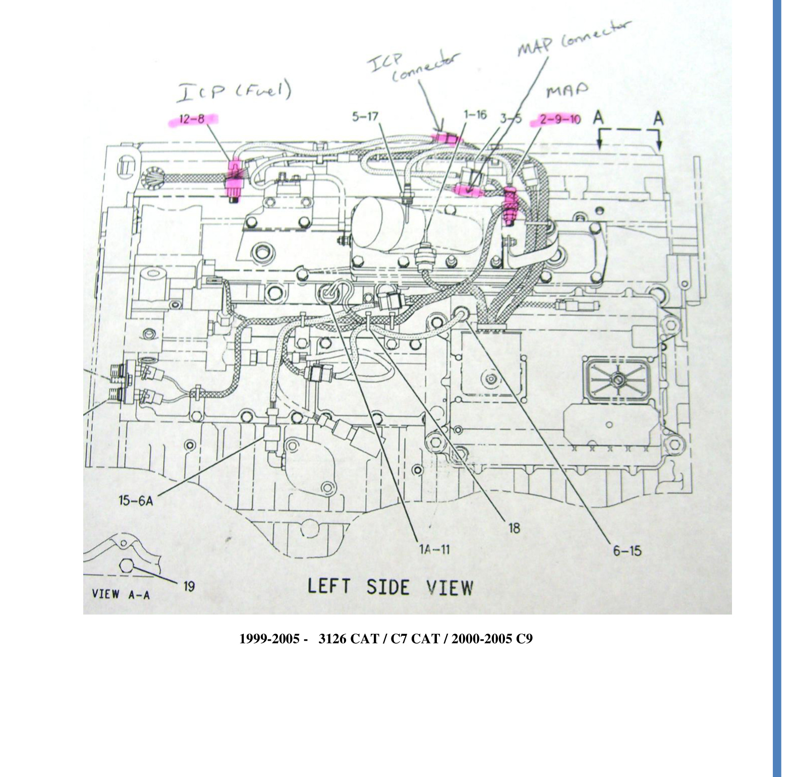
- 1999–2005 Cat 3126 / Cat C7
- 2000–2005 Cat C9
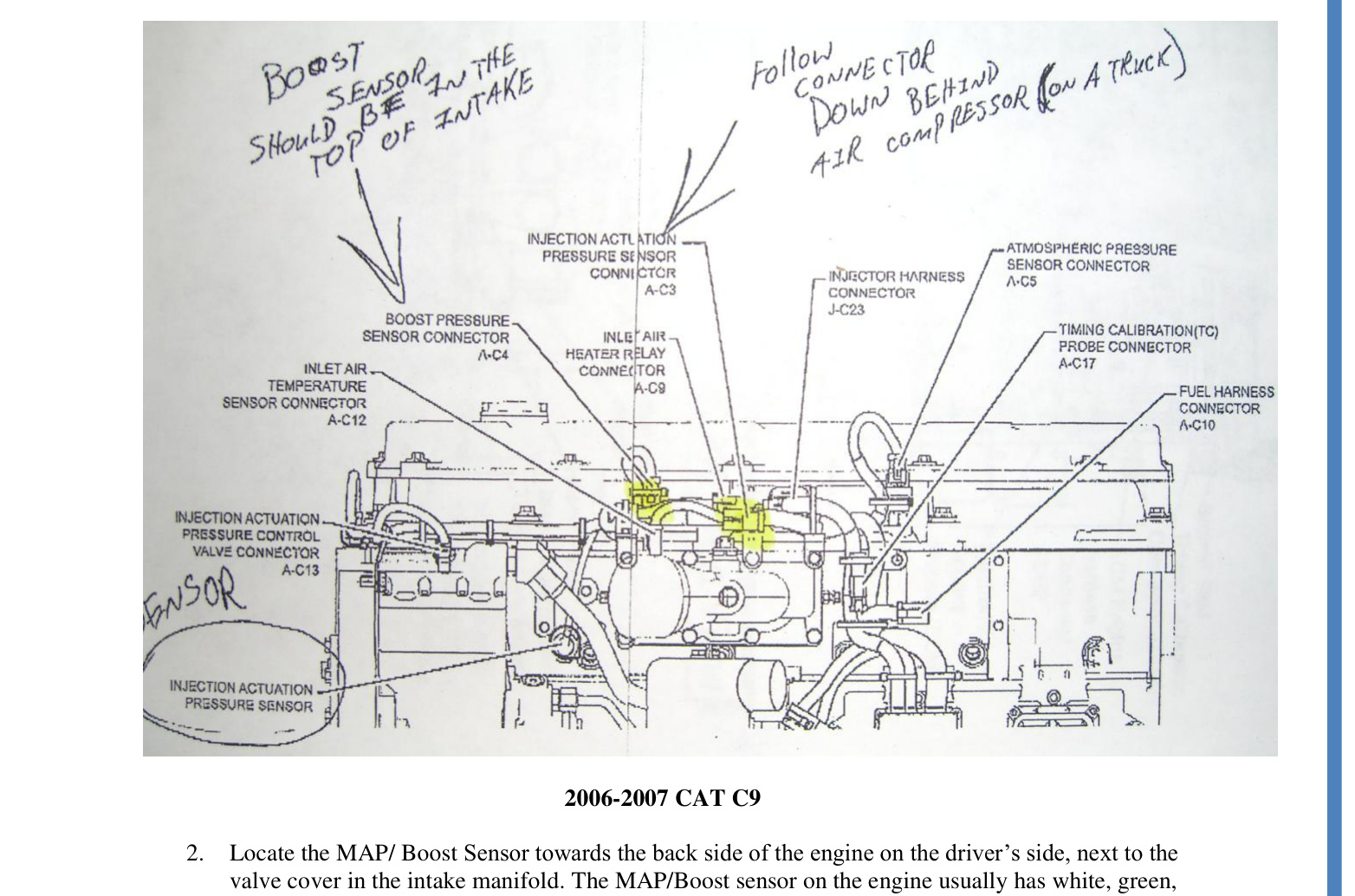
- 2006–2007 Cat C9 (off-highway only)
Kit Contents
Before you begin, confirm that the box contains all of the following:
- MP-8 Module
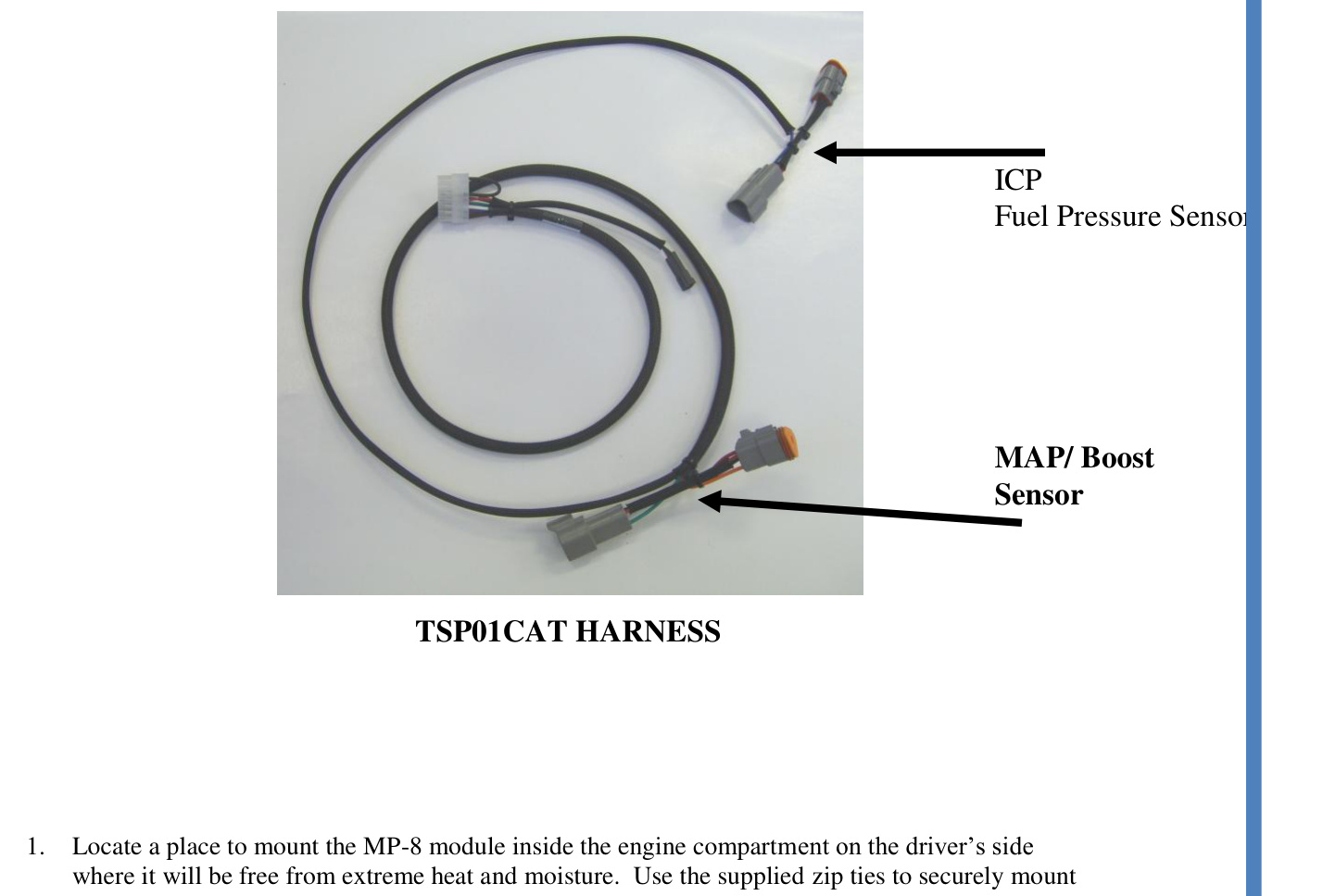
- Harness (TSP01CAT)
- Switch (TSP100)
- Zip ties (4)
Before You Begin
IMPORTANT: Read all instructions and fully understand them before installing your TS Performance MP-8 module.
WARNING: Disconnect the battery terminals and remove the keys from the ignition before installation.
NOTE: Apply dielectric grease to every electrical connection.
Installation
- Mount the MP-8 module. Locate a place to mount the MP-8 module inside the engine compartment on the driver’s side, where it will be free from extreme heat and moisture. Use the supplied zip ties to securely mount the module.
- Connect the MAP / Boost Sensor. Locate the MAP/Boost Sensor toward the back side of the engine on the driver’s side, next to the valve cover in the intake manifold. The MAP/Boost sensor on the engine usually has white, green and pink wires. Unplug the factory harness from this sensor and plug the harness from the MP-8 into it. On the TSP01CAT harness, the MAP connectors are the middle set of connectors, with the green and orange wires.
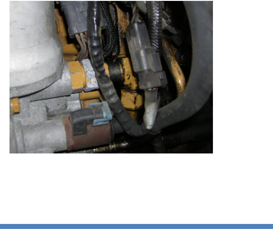
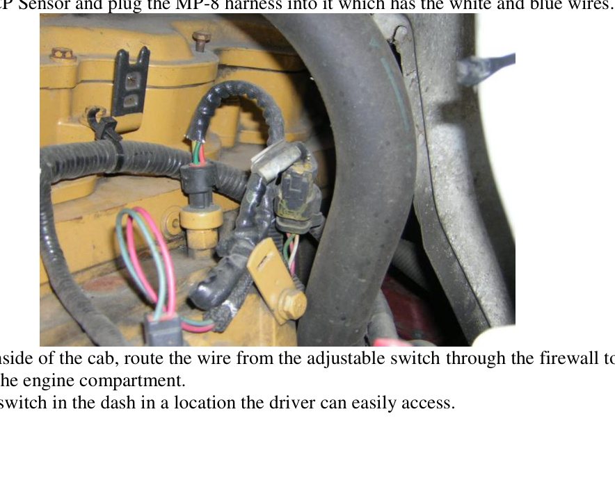
- Connect the ICP Sensor. Locate the ICP sensor directly in front of the MAP sensor, toward the front of the engine. The ICP connector on the engine usually has white, green and brown wires. Unplug the factory harness from the ICP sensor and plug the MP-8 harness — which has the white and blue wires — into it.
- Route the switch wire. From inside the cab, route the wire from the adjustable switch through the firewall to the module in the engine compartment.
- Mount the switch. Mount the switch in the dash in a location the driver can easily access.
Sensor Locations by Engine
Use the diagram that matches your engine to locate the ICP and MAP/Boost sensors before connecting the harness.
Operation
- HP increase of up to 30% over stock
- Decreases fuel consumption by up to 15%
- On-the-fly adjustable
- When removed, leaves no trace of modification
Power increases as you turn the switch clockwise, from 0–30% over stock.
Technical Support
If you have any questions about the product or the installation of the module, call TS Performance at (270) 746-9999.