Installation guide for the Pacific Performance Engineering (PPE) Stage 4 transmission kit for 2001-2005 Allison LB7/LLY 5-speed transmissions behind the Duramax. The kit is built to handle increased horsepower above factory specifications. Follow the steps carefully for a reliable build.
Download the Original PDF Manual
Applications
- 2001–2005 Allison LB7 / LLY transmissions
- 5-speed transmissions only
WARNING: This is a performance product that can be used with increased horsepower above and beyond factory specifications. Additional horsepower creates more stress on the drivetrain components, which could result in drivetrain failure. This kit should only be installed by a technician experienced in the rebuild of Allison transmissions.
IMPORTANT: Several steps in this kit apply to specific model years. Step 12 and Step 13a apply to 2001–2003 transmissions only (the TCC Limit and Lube Regulator were redesigned in 2004 — no change needed). Step 14b applies to 2004–2005 transmissions only. Read each step heading carefully before performing it.
C4 Clutch Modification
Step 1 — Disassemble the Rear Section
After the torque converter is removed, place the transmission into a holder or stand it up in a drain pan on the floor with the bell housing down. Then disassemble the rear section:
- Remove the rear extension housing as an assembly.
- Remove the park pawl pin, park pawl, and C5 return spring assembly.
- Remove the P3 sun gear and thrust bearing.
- Grasp the main shaft splines and lift straight up to remove the main shaft, P2 sun gear and spacer.
- Remove the P2 planet carrier and thrust bearing.
- Remove the C5 clutch pack and backing plate.
- Remove the P1 planet carrier assembly and thrust bearing — lifting up with a slight twisting motion leaves the P1 ring gear in place.
NOTE: Pay attention to the directional install of the Torrington bearing. Inverting bearings will result in extreme damage.
We recommend performing all C4 clutch modifications first.
Step 2 — C4 Clutch Pack
Remove the C4 retaining rings while compressing the backing plate, then remove the C4 clutch pack. Install the thrust bearing to the rear of the P1 carrier, retaining it with assembly gel, and install the P1 carrier into the P1 ring gear in the case. Lubricate and install the supplied C-4 piston with the air bleed hole in line with the top of the case at the 12 o’clock position (groove side up). Install the supplied C-4 clutch pack, starting with a Friction against the Apply Plate and alternating with Kolene® Steel.
When installing the Frictions and Steels, align the slots in each plate with the holes in the Apply Plate at the 12 o’clock position. Install 6 Frictions and 5 Steels, then install and compress the C-4 backing plate. Install the Spiral Ring, then the Snap Ring — the gap in the Snap Ring should be at the 1:30 position, aligning with the wide gap in the case. Clearance should be from .065″ to .075″.
Reassemble the rear section, being sure to align the slot in the Sun Gear Spacer with the lube hole in the Shaft Shoulder when installing the extension housing. The housing will be spring loaded for the last ½″ above the case — gently pull down evenly with a speed handle until flush, then torque to 45 ft-lbs.
TIP: We recommend soaking the Frictions in ATF for 30 minutes prior to installation.
Valve Body Removal & Disassembly
Step 3 — Remove the Oil Pan
Remove the oil pan (12 × 13 mm bolts).
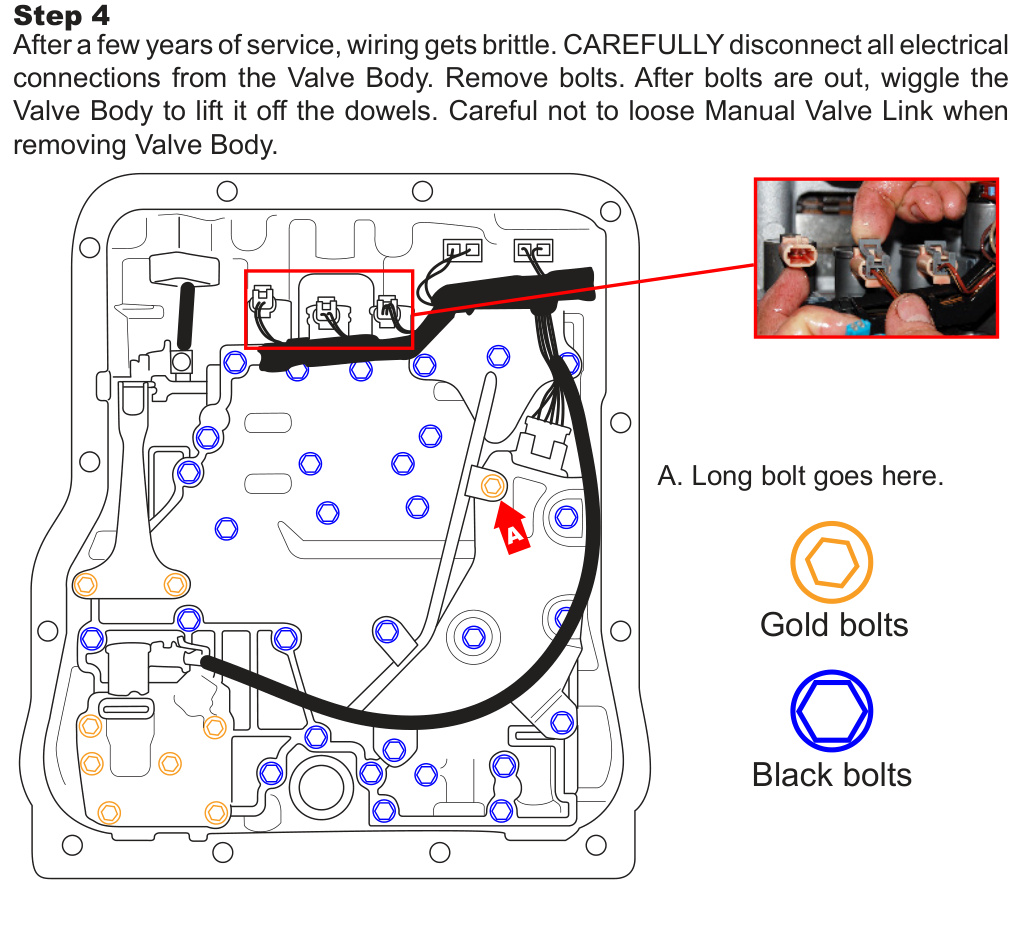
Step 4 — Remove the Valve Body
After a few years of service, wiring gets brittle. Carefully disconnect all electrical connections from the Valve Body. Remove the bolts, then wiggle the Valve Body to lift it off the dowels. Note the bolt colors and the long bolt location for reassembly.
CAUTION: Be careful not to lose the Manual Valve Link when removing the Valve Body.
Steps 5–8 — Access & Drill the Separator Plate
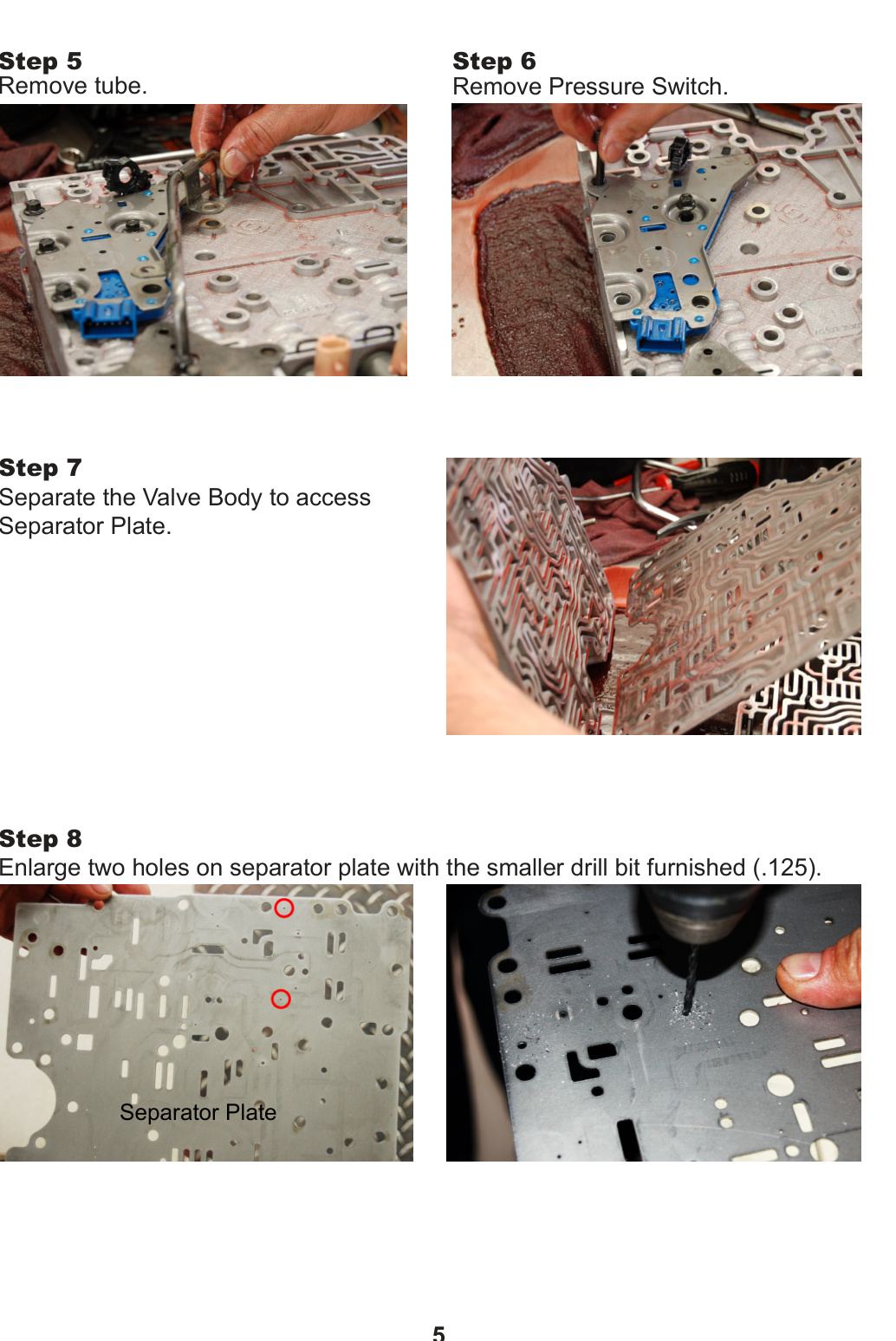
- Step 5: Remove the tube.
- Step 6: Remove the Pressure Switch.
- Step 7: Separate the Valve Body to access the Separator Plate.
- Step 8: Enlarge the two holes on the Separator Plate with the smaller drill bit furnished (.125).
Trim Valves & Bell Housing
Step 9 — Replace the Trim Valves
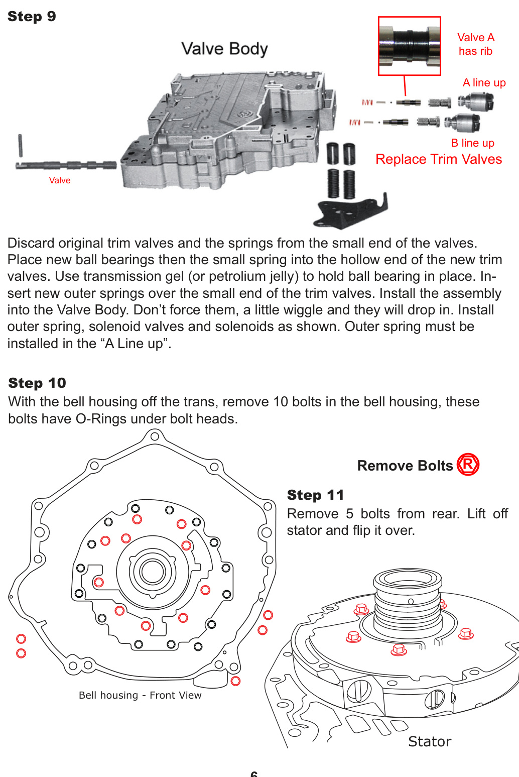
Discard the original trim valves and the springs from the small end of the valves. Place new ball bearings, then the small spring, into the hollow end of each new trim valve — use transmission gel (or petroleum jelly) to hold the ball bearing in place. Insert the new outer springs over the small end of the trim valves, then install the assembly into the Valve Body. Don’t force them — a little wiggle and they will drop in. Install the outer spring, solenoid valves and solenoids as shown.
IMPORTANT: The outer spring must be installed in the “A Line up.” Valve A has a rib.
Step 10 — Remove Bell Housing Bolts
With the bell housing off the transmission, remove the 10 bolts in the bell housing. These bolts have O-Rings under the bolt heads.
Step 11 — Remove the Stator
Remove the 5 bolts from the rear, then lift off the stator and flip it over.
Converter Relief & Flow Valves
Step 12 — Lube Regulator / TCC Limit Springs (2001–2003 only)
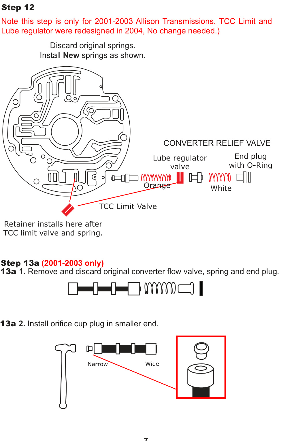
NOTE: This step is only for 2001–2003 Allison transmissions. The TCC Limit and Lube Regulator were redesigned in 2004 — no change needed.
Discard the original springs and install the New springs as shown. The retainer installs after the TCC Limit Valve and spring. The Lube Regulator Valve uses the Orange spring; the Converter Relief Valve uses the White spring with the End Plug and O-Ring.
Step 13a — Converter Relief Valve (2001–2003 only)
- Remove and discard the original converter flow valve, spring and end plug.
- Install the orifice cup plug in the smaller (narrow) end.
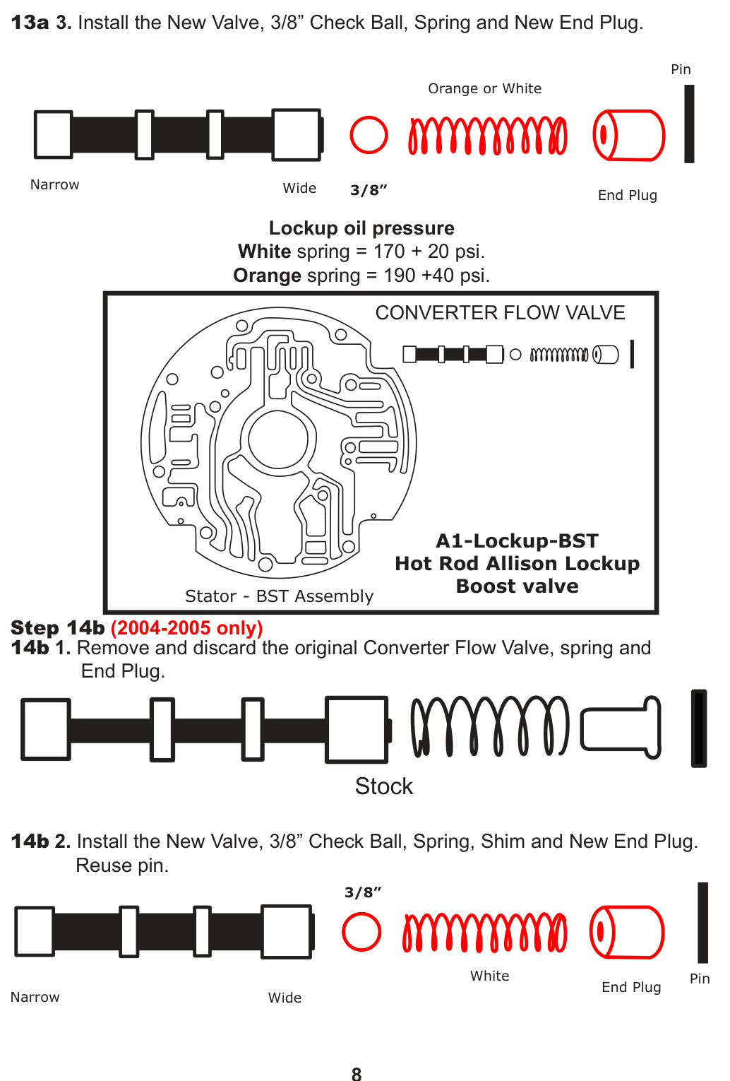
- Install the New Valve, 3/8″ Check Ball, Spring and New End Plug.
Step 14b — Converter Flow Valve (2004–2005 only)
- Remove and discard the original Converter Flow Valve, spring and End Plug.
- Install the New Valve, 3/8″ Check Ball, Spring, Shim and New End Plug. Reuse the pin.
Lockup oil pressure (A1-Lockup-BST “Hot Rod Allison” lockup boost valve): White spring = 170 ± 20 psi; Orange spring = 190 ± 40 psi.
Main Regulator & Rotating Module
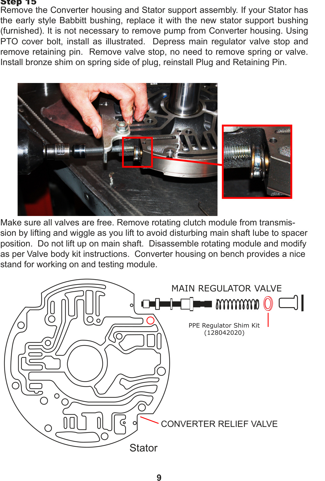
Step 15 — Stator Support & Main Regulator Valve
Remove the Converter housing and Stator support assembly. If your Stator has the early-style Babbitt bushing, replace it with the new stator support bushing (furnished). It is not necessary to remove the pump from the Converter housing. Using the PTO cover bolt, install as illustrated. Depress the main regulator valve stop and remove the retaining pin, then remove the valve stop (no need to remove the spring or valve). Install the bronze shim on the spring side of the plug, then reinstall the Plug and Retaining Pin.
Make sure all valves are free. Remove the rotating clutch module from the transmission by lifting and wiggling as you lift, to avoid disturbing the main shaft lube-to-spacer position. Do not lift up on the main shaft. Disassemble the rotating module and modify it per the Valve Body kit instructions. The Converter housing on the bench provides a nice stand for working on and testing the module.
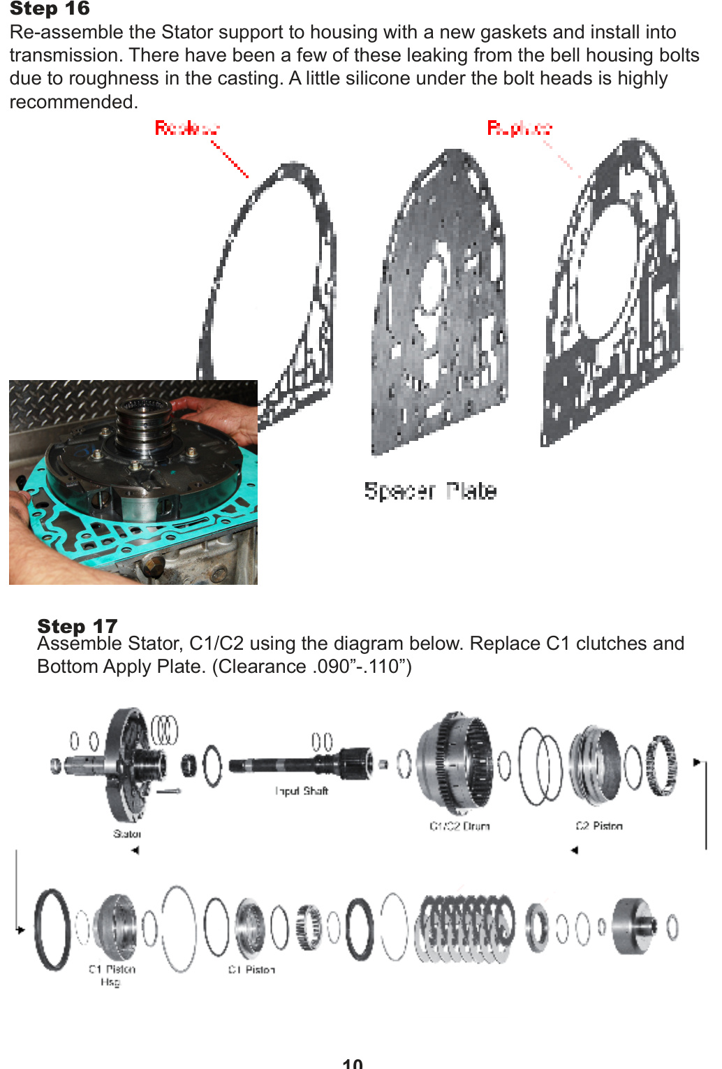
Step 16 — Reassemble the Stator Support
Reassemble the Stator support to the housing with new gaskets and install it into the transmission.
CAUTION: A few of these have leaked from the bell housing bolts due to roughness in the casting. A little silicone under the bolt heads is highly recommended.
Step 17 — Assemble Stator C1/C2
Assemble the Stator, C1/C2 using the diagram below. Replace the C1 clutches and Bottom Apply Plate. Clearance should be .090″–.110″.
C2 Piston Modification
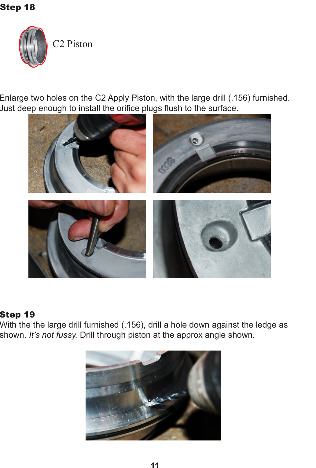
Step 18 — Drill the C2 Apply Piston
Enlarge the two holes on the C2 Apply Piston with the large drill (.156) furnished — just deep enough to install the orifice plugs flush to the surface.
Step 19 — Drill the C2 Piston Passage
With the large drill furnished (.156), drill a hole down against the ledge as shown. It’s not fussy — drill through the piston at the approximate angle shown.
C1/C2 Spring Cage & Clutch Assembly
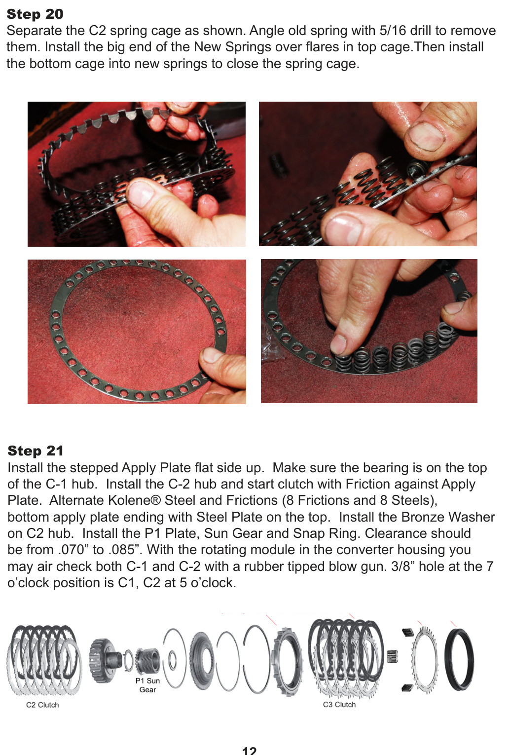
Step 20 — C2 Spring Cage
Separate the C2 spring cage as shown. Angle the old springs with a 5/16 drill to remove them. Install the big end of the New Springs over the flares in the top cage, then install the bottom cage into the new springs to close the spring cage.
Step 21 — Assemble C1/C2 Clutches
Install the stepped Apply Plate flat side up. Make sure the bearing is on the top of the C-1 hub. Install the C-2 hub and start the clutch with a Friction against the Apply Plate. Alternate Kolene® Steel and Frictions (8 Frictions and 8 Steels), bottom apply plate ending with a Steel Plate on the top. Install the Bronze Washer on the C2 hub, then install the P1 Plate, Sun Gear and Snap Ring. Clearance should be from .070″ to .085″.
TIP: With the rotating module in the converter housing, you may air-check both C-1 and C-2 with a rubber-tipped blow gun. The 3/8″ hole at the 7 o’clock position is C1; C2 is at 5 o’clock.
Final Assembly
Step 22 — C3 Clutch & Module Install
Depress the C3 Top Plate and remove the Snap Ring, Top Plate, Clutch Pack, Apply Plate, Springs and C3 Piston. Install the furnished C3 Piston (bleed hole at the 12 o’clock position) and install the return springs onto the furnished apply plate. Install the Apply Plate groove side up. Install the Frictions and Steels in the same manner as C4 (5 Frictions and 4 Kolene® Steels), aligning the slots with a 12 o’clock hole position. Install the furnished C3 Pressure Plate, depress the plate and install the Snap Ring with the gap at the 1:30 position. Clearance should be from .065″ to .070″.
Retain the bearing with assembly gel, then install the rotating module, making sure the module is fully seated. Install the Converter housing with a new gasket and torque to 45 ft-lbs. Check end play at the turbine shaft (.011″–.060″). Perform the Valve Body modifications per the Valve Body Kit instructions.
NOTE: To read and clear codes, use PPE’s Xcelerator Tuner. The transmission relearn procedure can take up to 2 hours; PPE’s Xcelerator Tuner can speed up this process using the re-set transmission procedure.
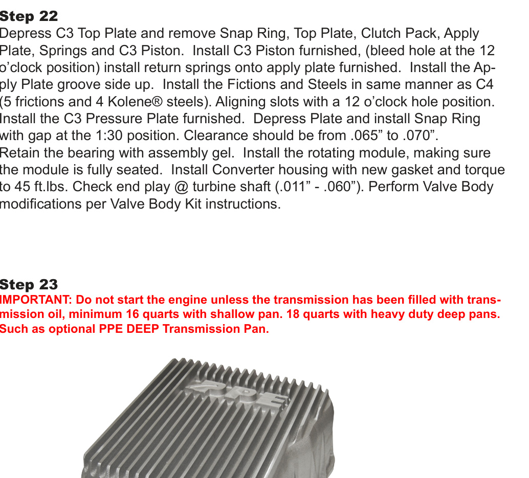
Step 23 — Fill with Transmission Fluid
IMPORTANT: Do not start the engine unless the transmission has been filled with transmission oil — minimum 16 quarts with a shallow pan, or 18 quarts with heavy-duty deep pans such as the optional PPE Deep Transmission Pan.
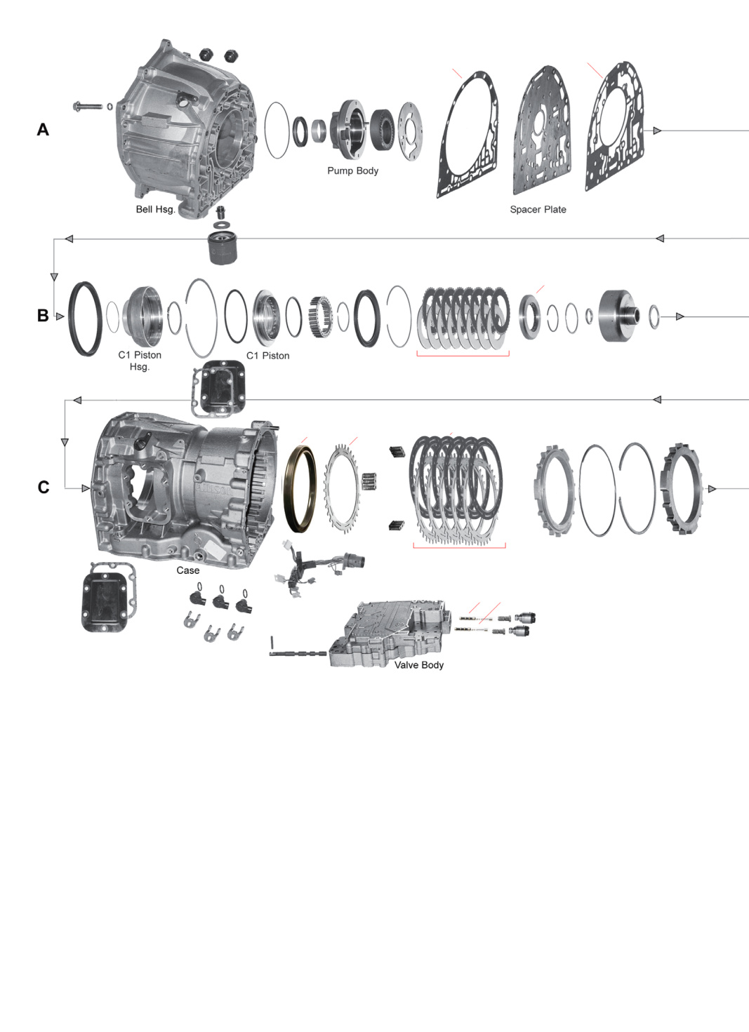
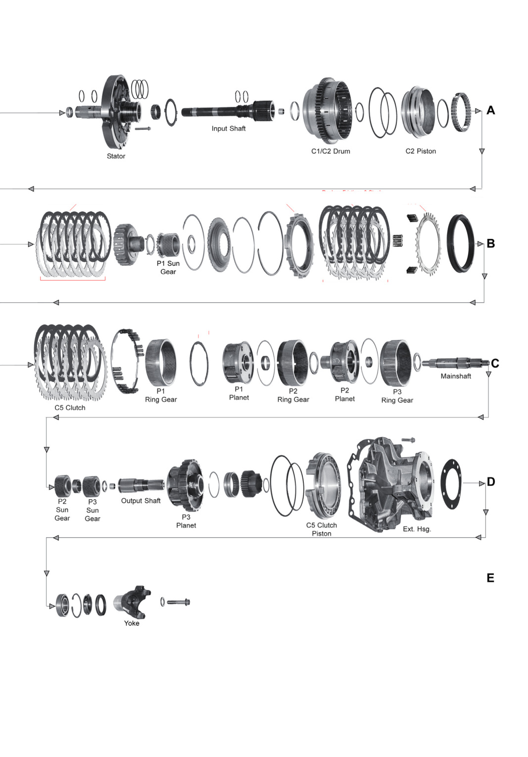
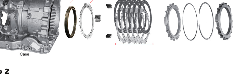
Transmission Assembly Reference Diagrams
Use these exploded views as a reference for component order and orientation during reassembly.