
Fitting instructions for installing your new South Bend clutch (kits #1944, #1939 and #1950). Before replacing the clutch it is vital to diagnose the cause of the original failure. Following these instructions ensures correct installation and protects your warranty.
Download the Original PDF Manual
WARNING: Do not use these clutches in any situation where engine RPMs may exceed the manufacturer’s specifications — a pressure plate could explode unexpectedly, causing serious injury or death to vehicle occupants and bystanders. The clutch cover and bell housing will not protect against exploding pressure plates. Refer to the Application Catalogue for correct fit.
IMPORTANT: Failure to observe these instructions when fitting your South Bend Clutch will void any warranty. Get it right the first time.
Do’s and Don’ts
Never
- Force the input shaft into the disc hub — it will bend the disc or scar the splines.
- Allow the weight of the transmission to hang on the disc.
- Touch the friction surface of the disc with greasy hands.
- Use an impact wrench to tighten the pressure plate mounting bolts.
- Install a new disc without replacing the pressure plate and release bearing.
Always
- Use the proper alignment tool.
- Check the fit of the disc hub splines to the input shaft before installation.
- Resurface or replace the flywheel.
- Tighten pressure plate bolts in a “star” or criss-cross pattern, one turn at a time.
Torque Specifications
- Pressure plate to flywheel: 18–20 ft-lbs (general spec ~20 ft-lbs).
- Flywheel to crank: 95–105 ft-lbs (threadlock recommended).
Flywheel-to-Crank Torque by Application
- 87–94 non-PowerStroke flywheel: 45–49 ft-lbs.
- 94–03 PowerStroke flywheel: 87–91 ft-lbs.
- 04–08 6.0 & 6.4 flywheel: 45–49 ft-lbs.
NOTE: This unit may appear different from your old part due to design differences between manufacturers. It will function properly in your vehicle.
Pre-Installation Checks
- Diagnose the original failure first. It is vital to diagnose the cause of clutch malfunction before replacement — check the hydraulic system, bearing free travel, clutch cable and oil leaks, and look for any signs of red dust when the old clutch is removed. Any or all of these problems must be corrected before installing a new clutch.
- Confirm the clutch is correct for the application. If you’re unsure, consult your South Bend Clutch supplier — fitting a clutch to the wrong application will void the warranty.
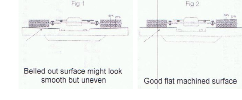
- Inspect and prepare the flywheel. The flywheel must be replaced or machined flat (see Figs 1 & 2, max 0.03 in.) or the warranty will be void. Check the spigot bearing or pilot bush and replace if necessary. Note that pilot bush noises are more apparent when the engine and transmission are cold (e.g. in the mornings).
- Check for shipping damage and prep the splines. Clean the gearbox main drive shaft splines, then confirm the clutch disc slides freely on the shaft. Lightly grease the shaft splines with high-melting-point grease. Ensure the bell housing is degreased and free of dust, and that fibers from the worn clutch are removed. For a large pull-type clutch, check the ID of the bearing head for the correct spline size before installation. Lack of lubrication / dry splines will cause failure to disengage gears and clutch drag.
- Inspect the release components. Check the clutch release fork for cracks, the clutch cable for stretch, and the release bearing guide tube for wear. Lightly grease the outside diameter of the guide tube to allow smooth sliding of the bearing carrier. After installing the bearing on the release fork, move the fork forwards and backwards (in both directions) to confirm the bearing is secure and will not fall onto the clutch fork or bell housing before refitting the gearbox.
Flywheel Resurfacing
Flywheels should not be lathe cut. The OEM taper on the flywheel runs approximately 0.002″–0.003″ from outside to inside; this does not need to be matched — flat is preferred with this clutch. Resurface flywheels with a grinder specifically built for grinding flywheels. Do not aim for a rough finish — the smoother the better. Make sure the pressure plate bolt holes are thoroughly cleaned after resurfacing; running a thread chaser or tap will ensure the threads are clear of all debris.
Installation
- Fit the pressure plate assembly. Place the clutch cover / pressure plate assembly over the clutch disc after confirming the disc is the right way around and that the hub section of the disc does not foul the casting of the clutch cover assembly or the flywheel. A suitable clutch aligning tool ensures correct alignment, eases installation and avoids spline damage (burrs on splines are a major cause of difficult gear disengagement). Ensure the pressure plate dowels are aligned to the cover.
CAUTION: Tighten bolts in a diagonal (star / criss-cross) pattern and never use air tools to install a clutch cover assembly. Torquing bolts in an uneven pattern can, in some cases, cause the lever strut to dislodge from the pressure plate casting.
- Check the diaphragm/lever tip position. Once the pressure plate is torqued securely to the flywheel, ensure the diaphragm tips (or, for a lever-type cover assembly, the release lever tips) are in a parallel or slightly upward position (see Fig 3) and do not go over-center of the parallel position.

Fig 3 — diaphragm tip position. Position B is OK; positions A and C are NO GO. NOTE: Some prying may be required to level the fingers of the clutch. Use a small pry bar positioned between the cover and the diaphragm spring to force the high fingers down to a uniform position. - Refit the gearbox. Take care not to bend the clutch disc. Never hang the gearbox off the clutch disc or use force to align the gearbox shaft.
- Tighten the bell housing. Check that all bell housing dowels are in the correct position, then tighten the bell housing bolts. Ensure there is no dirt or foreign material between the mating surfaces of the engine and the bell housing.
- Adjust the clutch. Perform any clutch adjustments to the vehicle manufacturer’s specifications, and always reset the clutch master cylinder push rod to obtain a comfortable pedal release position. (Having the clutch take up as close as possible to the floor prevents clutch shudder and is preferred by most drivers.) Keep in mind that the diaphragm tip position has changed with the new clutch.
Clutch Fork Orientation
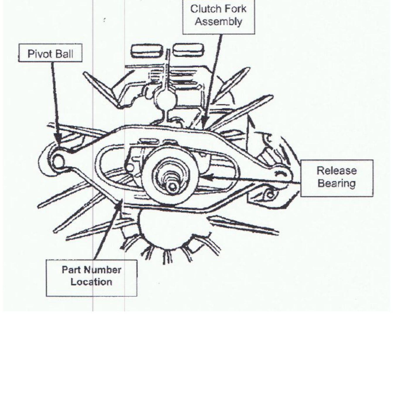
On some vehicles the clutch fork can be installed in the reverse position. When installed incorrectly, the result will be a growling noise from the bell housing and/or a no-release condition. Refer to the figure below for the correct fork orientation during assembly.
When the clutch fork is installed properly, the fork part number will be on the left side of the transmission input shaft. The left side of the transmission is the side where the pivot ball is located (see the figure).
Troubleshooting Disengagement
If you are unable to obtain disengagement when a new clutch is fitted, always check the clutch cable first — start your checking process by replacing the cable. If it is a hydraulic clutch, check the clutch master cylinder and slave cylinder, ensuring there is no air in the system. This is essential to obtain maximum travel for disengagement.
Break-In and Road Test
ATTENTION: High-performance clutches require a break-in period. 200 miles of normal city (stop-and-go) driving should properly break in your clutch. If slipping occurs, resume normal driving for 50 miles.
- Road test the vehicle and never abuse a newly fitted clutch.
- Allow a 750-mile break-in.
- Adjust free travel at 750 miles and again at 1,500 miles.
- Thereafter, adjust free travel every 10,000 miles.
WARNING: Failure to follow the above instructions will negatively affect the performance of your clutch and may void your warranty.